Friday 5 August 2022

Rear Axle Reassembly - Part 9 - Hubs On....Finally!

Finally, the day has come when, having messed around for so long, I am hoping to get the rear hubs onto the car at last.  I had already purchased some of the new parts required for this momentous day from SNG Barratt many moons ago, as per the table below:


The first operation of the day was to secure the brake shoe mounting blocks to the backing plates using some M6x10 screws with spring washers.  I added a dobble of Loctite to these for good measure.

Brake shoe mounting block...mounted!

My new spacer tubes were inserted to place, the backing plate placed over the hub, and secured using new fixings all around.  Each plate needs two M10 screws and two M6 screws; the M10s come with thread lock compound already applied to the threads, I added some extra to the M6 screws.  These were tightened evenly using TPS45 and TPS25 bits until the backing plate was snug against the hub carrier.

Lower M10 Mounting Bolts with factory applied thread lock

I then spent some considerable time grappling with the installation of the handbrake shoes and springs (Handbrake Part 1) before it was time to reinstall the hubs.

These were given a liberal application of grease before being pushed firmly into place.  The hubs were then turned over and the ABS ring tapped onto the back of the hub using a large piece of timber as a suitable drift and a large hammer to provide the force!

Hub greased prior to insertion...

...ABS ring tapped firmly back into place...

...and one completed hub ready to go onto the car!

Finally, it was time to get the hubs on the car!

First step - install the hubs onto the lower wishbones.  This required the use of two new spacers per hub, which were installed on the face of each of the fulcrum bearings with a good smear of copper grease to hold them in place during installation.  I just ordered four new 3.955mm spacers (the same size as my donor spacers) since (according to the AK gospel of Jon Freeman) the shimming / preload of the lower fulcrum bearings is not important so long as the wishbone bracket is pulled tight against the hub.  As it was, the new spacers were just about the right thickness, and just needed a gentle tap with a soft mallet to ease the lower part of the hub into the wishbone bracket.  I gave all the contact surfaces a light smear of copper grease prior to installation.

The lower fulcrum bolt was given a very liberal application of copper grease, tapped gently through the lower wishbone mount, and secured with an M14 Nyloc and washer - just snugged into place for the moment.

The driveshafts were then installed onto the differential and held in place with plain 7/16 inch nuts.  I installed the driveshafts without any shims/spacers between then and the differential flange; the camber will be checked and the required shim thickness worked out next.

The drive shafts were then installed into the hub, which required a bit of manipulation to get the relative angles correct to allow the shaft to slide into the hub, before securing with the original cone washer and drive shaft nut.  The cone washer, drive nut, and differential flange nuts will all be replaced with new items once the camber has been set and final shims installed.

Hub and spacers tapped into lower wishbone mount

The last time I can say it - a heavily greased shaft!

Differential flange set up with no spacers/shims

Hub installed - it feels like a major milestone!

The final finishing touch was to make some plates to cover the hole for the ABS sensor in the top of the hub carriers.  Most people seem to leave these open but that just offends my sense of perfection!  

I made up a greasy finger paper template, stuck this to a piece of 2mm sheet steel, and cut/filed this down to the required profile.  The fixing hole locations were marked out and drilled with a 6mm drill.  The plates were of course treated to some candy red powder coating (as with all the other bits that won't be seen on the final car...).  I also cut out a couple of gaskets from rubber sheet, to match the outline of the plates, and then these were fixed in place with some stainless steel M6 button head screws with spring washers.

Greasy finger paper template

Powder-coated plates and rubber gaskets

Cover plate fixed in place

A very productive day - time for a well-earned beer me thinks!

Tuesday 2 August 2022

Rear Axle Reassembly - Part 8 - Tubeway Army

 With my rubber gaskets sorted, it was time to get the brake back plates bolted onto the hub carriers. 

Although as I was mocking up the parts for reassembly, I noticed that the brake back plates are not particularly stiff where the handbrake cable passes through them.  The AK handbrake has come in for a bit of stick on many forums for its rather marginal performance.  My thought was that if the back plate flexes from the applied tension in the handbrake cable then this could be a factor in reducing the efficiency of the system.

The original Jaguar setup had a small spigot tube bolted to the back of the backing plate, through which the handbrake cable passed, and then a plastic clip between this tube and the hub carrier to hold the handbrake cable in place.  It is conceivable that this arrangement could offer some sort of limited bracing between the hub and the back plate (although that's possibly wishful thinking).  In any case, this option was not available to me as my original spigot tubes are now a fine lacework of rust and replacements are not available.

A small spot of tin worm...

My solution was to make a couple of spacer tubes to sit between the hub carrier and the backing plate that would serve to brace the backing plate and reduce any flex during application of the handbrake and also protect the exposed part of the handbrake cable from the elements.

This was an opportunity to press my "new" lathe into action.  This is a story in itself, but the short version is I foolishly put a bid on an old Myford ML7 lathe on the well-known auction site thinking that I would be outbid...and ended up winning the bid.  To be fair, it was in pretty good condition and came with lots of tooling, so it was a very reasonable (if unexpected) purchase.

I made some measurements and knocked up a quick CAD sketch of my intended solution, being a tube with a flange at each end to bear onto the hub carrier at one end and the handbrake mounting block at the other, with a small stub at each end to locate tube in position and a hole large enough to allow the clevis on the end of the handbrake cable to pass through.

Original Design Sketch

The spacers were machined from 25mm aluminium bar stock, faced and turned to size, a 12mm hole drilled down the middle, and finished off with a boring bar (twist drill bits do not produce a true circular hole).  I made the stubs at each end slightly longer than my original sketch (to facilitate machining) and I also machined a groove in the hub carrier end to allow the use of an O-ring to fully seal the tube to the hub carrier.

Aluminium bar after initial facing and turning - with tail support

Machined down for stub at one end

Location of flanges marked out

Spacer waisted out between flanges and larger stub formed

Drilling 12mm dia hole after 6mm pilot 

Completed Spacer Tube

Spacer in place between hub carrier and back plate

And to finish off this completely over-engineered component that will probably never be seen by human eyes again, I powder-coated it in the obligatory metallic red that I have chosen for all such parts on the car!

Further unnecessary bling!

Now I think the hubs can finally be fully reassembled.


Wednesday 22 June 2022

Rear Axle Reassembly - Part 5 - Rear Wishbones

 With the hubs done and ready to be installed, I turned my attention back to the chassis and the installation of the rear wishbones.

The rear wishbones are new items supplied by AK.  I bought new inner pivot bolts from SNG Barratt as I ended up "slightly" damaging the original ones whilst stripping down the donor axle/rear sub-frame.

The AK setup also requires the use of a spacer tube; these didn't come with my X300 axle but I managed to source a spare pair from Ben at Simply Performance.

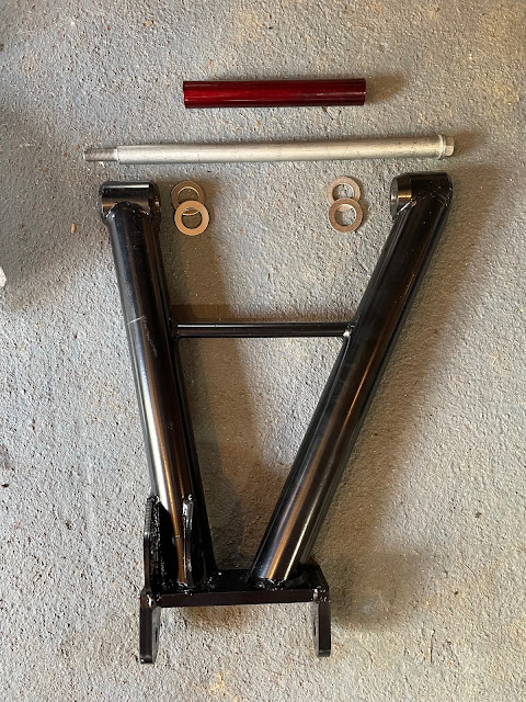
Looking at the AK Build Manual, the installation of the wishbones is fairly straightforward.  The (new) outer pivot bolt is passed through the rear of the new wishbone, through two washers, through the rear differential tie bar, through the spacer tube, through the front wishbone mount, through two more washers, and finally, through the differential pendulum mount before being secured with a final washer and bolt.  The pivot bolts were given a liberal coating of copper grease prior to installation.

Simple.

Wishbone, new pivot bolt, washers and spacer tube

Well, it was simple, apart from a couple of small issues.

First, the AK Build Manual calls for the use of 1 1/2" by 7/8" washers.  But for some annoying reason, they don't supply these washers.  This is a complete pain because despite exhaustive internet searching I could not find this size washer outside of the US of A.  Fortunately I was prepared.  Having read Richard Chippendale's blog and his solution of using M22 washers instead, I had already pre-ordered a pack of suitable replacement size washers.

Close-up of wishbone mounting configuration...

...and view of installed wishbone.

The second issue is that the AK Build Manual suggests the use of an M12 is needed for the end of the inner pivot shaft.  This is incorrect.  Had I read/remembered Richard's blog better, I would have already known this.  But I was not prepared for this eventuality, and so there was a short break in the proceedings for another order with SNG Barratt.

(I couldn't actually find the original fulcrum nuts from my donor axle.  But even if I had, they were so rusty from when I removed them, that I wouldn't have wanted to re-use them in any case.)


The nuts are actually I believe an M14 thread.  However, the proper Jag nuts have a bit of a skirt on them.  This helps spread the load more evenly onto the washer on the end of the fulcrum bolt; this washer bears onto the metal sleeve in the bushing in the pendulum mount and a "normal" size bolt might cause some distortion of the washer when tightening.

Nice flange...

Once these arrived it was a simple job to pop them onto the end of the fulcrum bolt, along with an M14 washer and fasten up hand tight for the moment.  I will torque these up fully to around 70-75lb-ft / 90-102Nm once the wheels are on and the suspension is partially loaded.

Next step is to get the drive shafts reassembled before I can refit the hub carriers.

Tuesday 21 June 2022

Rear Axle Reassembly - Part 7 - Pig Pen, this here's Rubber Duck...

Before the rear hubs can be reinstalled into the carriers the brake backplates, which hold the handbrake mechanism in place, need to be fixed to the hub carriers.

In my view, there is a distinct flaw in the Jaguar design for this set-up.  The hub carriers are aluminium and the brake backplates are steel.  Fixing the two dissimilar metals together results in a chemical reaction, known as galvanic corrosion.  This accelerates the breakdown of the natural coating of the aluminium and produces aluminium oxide (remember all that white crusty crud under the backplates when the hubs were stripped down).

This process is exacerbated by moisture and salt (like er...road salt) and so to ensure that the conditions for this galvanic corrosion are fully optimised, the Jaguar engineers decided to leave the aluminium mating face of the hub in a rough cast form to really allow the ingress of water, dirt and salt to take place, and then to ensure that it remains trapped in place to do its evil deed. 

A haven for dirt, debris and road crud!

A number of solutions have been proposed on the various build blogs that I have perused; including just bolting it all back together, a liberal application of copper grease, or the use of the dreaded RTV silicone sealant.

I decided to try an alternative solution and go with a rubber gasket.  This should keep the two metal components separated to reduce the opportunity for galvanic corrosion and also, hopefully, keep water and crud out of various nooks and crannies resulting from the rough cast face of the aluminium hub.

I made up an initial paper template. The centre hole was sized by placing the backplate on a sheet of paper and simply running a pencil around the edge of the hole.  This was cut out using a sharp knife and placed onto the hub.  Using a suitably greasy finger, I rubbed over the paper to trace the shape of the edge of the hub and the screw mounting holes.  The template was then completed by trimming the outer edge and screw holes.

Why you shouldn't wash your hands.....

Final template

I then stuck the paper template down onto a sheet of 1mm thick rubber sheet (purchased from that well-known internet auction site).  I used a scalpel to cut around the edges of the template and create the rubber gasket.  The template was stuck down a second time and the process was repeated to create a second gasket.

Template stuck down onto rubber sheet...

...and trimmed to create gasket.

A perfect fit!

Now I have sorted this issue I can press on with reassembly...


Update - Project Snake is still alive (again....)

So in May 2021 I put up a post of hope - hope that I would get some serious work done on the Cobra.  It didn't happen...

I did a few bits here and there (some belated posts to follow) but I had a major distraction with the decision to remove some existing timber decking in my garden and replace it with some stone paving.  As always, the project spiraled and took about 10 times longer to complete than planned (actually at the time of writing it is still not technically complete as the lawn still needs to be relaid...).  Still, my wife is now very happy so maybe, with what is left of this year, I will be able to crack on with the Cobra!

Update photo - the eagle-eyed will spot that it looks almost exactly the same as the update from last year - just wearing slightly more dust!


Wednesday 23 June 2021

Rear Axle Reassembly - Part 6 - Drive Shafts

 With the rear wishbones installed, the last thing needed before the rear hub carriers can be installed and the rear axle set-up completed, is to assemble the drive shafts.

AK provide shortened driveshafts as part of the kit.  These need to be mated to the donor splined axle shaft and differential connection plate using new universal joints to complete the drive shaft assembly.

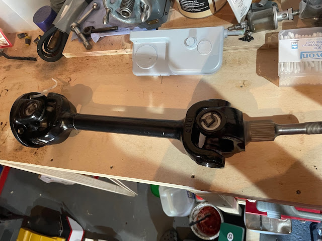
Shortened Drive Shaft - spot the join!


I ordered the replacement universal joints from SNG as per the part numbers below.  The end bearing cups need to be removed from the spider for installation, with care taken not to disturb the needle roller bearings in the cups.  Prior to assembling anything I put a generous smear of copper grease on all the openings in the various components.


Replacement UJ Kit Contents

Bearing Cup Removed - take care not to disturb the needle rollers


My hydraulic press was buried behind several boxes of Cobra parts so I was originally intending to be a bit lazy and follow the AK method of using a vice to assemble the UJs.  However, the initial attempt to wind the first bearing cap into one side of the diff connection plate using the vice resulted in the cap getting slightly misaligned and jammed; I wasn't happy with hammering on the vice lever to force the cap into place so I resorted to clearing the garage up to give access to my press.

I also found that the AK method of pressing one bearing cap into place first, and then inserting the spider didn't work.  Maybe I pushed the cap in slightly too far but there seemed insufficient space to work the spider into the partially inserted bearing cap and the other side of the connection plate.  The solution was to hold the spider in place while the first bearing cap was pressed into place, turn the plate over and press the other side bearing cap fully into place (i.e. so that the circlip groove was visible) and the first circlip could be inserted.  Then the piece was turned over again, and the initial bearing cap pressed in sufficiently to allow the second circlip to be inserted.

Holding spider in place...

...first bearing cap is pressed into place.

Bearing cap pressed in flush with outside of diff plate

Other side bearing cap pressed in fully and circlip installed


TOP TIP - make sure that when you install the spider, that, having installed the grease nipple, it is facing towards the half shaft.  This makes access for greasing of the nipple once it is installed far easier.  Once again you may ask me how I know this (although its not a disaster if the nipples end up facing the other way).

New grease nipple installed and facing towards driveshaft...


This process is then repeated to connect the diff plate to the new shortened AK half shaft; the diff plate / spider assembly is held in place while the first bearing cup is pressed into the half shaft until flush.  Then the assembly is turned over and the second bearing cup pressed fully into place in the half shaft and circlip installed.  Then the first cup is pressed fully in and its circlip installed.

The whole process was then repeated to attach the splined axle shaft to the half shaft.

First bearing cup pressed in to connect diff plate to half shaft

Rinse and repeat for the splined axle end...

...and one completed drive shaft!

I have no intention of having to disassemble the drive shafts ever again, but should that need ever arise, I put a smear of copper grease around all the circlips to give them a bit of added protection against the elements and possibly give a fighting chance of easy removal at some point in the (distant) future.

I also greased up the universal joints with a grease gun filled with a lithium based bearing grease, pumping the grease in until it was just starting to seep out of all the rubber seals of the UJ bearing cups.

And with that, reassembly of the drive shafts is complete!

Friday 4 June 2021

Rear Axle Reassembly - Part 4 - Grease is the Word..!

So with all the bearing races installed into the rear hubs, the hub pre-load checked, and the correct spacers ordered, now I can crack on with greasing the bearings and finally re-building the hubs, yes?

Actually, yes I can!

Installing the hub bearings is very straightforward and exactly as per the AK Build Manual.

A generous smear of grease applied to the outer race

Grease vigorously massaged into the outer race

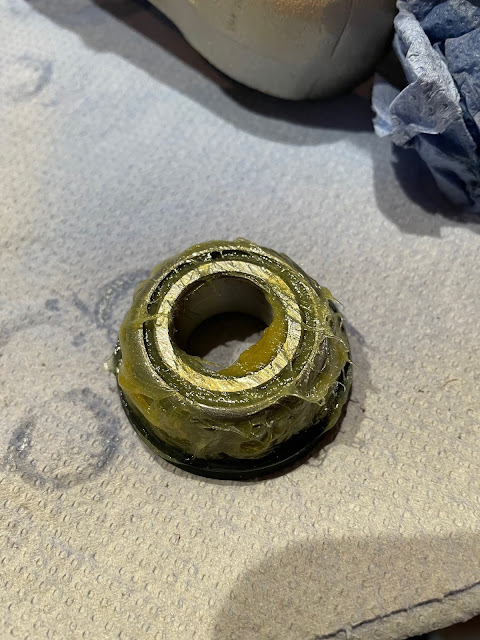
Even more grease smeared onto front face of bearing

The outer oil seal was then tapped into place

It's pretty much the same for the inner bearing, remembering to include the fixed spacer and the correctly sized 3.02mm adjustable spacer.

3.02mm Spacer freshly delivered from SNG Barratt

Inner bearing packed with grease and inserted in place with extra grease!

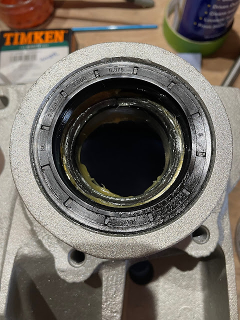
Tapping inner oil seal into place completes the job!

Next up is to install the new fulcrum bearings and new pivot pin sleeves.  On the original Jaguar set up the fulcrum pivot pin has an eccentric head which engages in a machined groove in the rear wishbone and, depending on the rotation of the bolt head, moves the bottom of the rear hub in or out to set the rear toe-in. This arrangement is dispensed with in the AK set-up.  

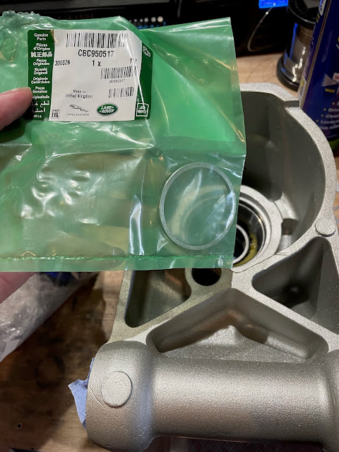
However there is still a need to install spacers between the fulcrum bearings and the rear wishbone.  The AK Build Manual simply states to reinstall with the original spacers from the donor vehicle. All well and good unless, like me, you somehow threw away / lost some of the original spacers when disassembling the rear axle.

All is not lost as you can buy new spacers easily from SNG Barratt or other Jaguar parts suppliers.  But, like the rear hub spacer, they come in a variety of thicknesses.  Further internet investigation revealed that the rear fulcrum bearings also need to be installed with a certain amount of pre-load.  Except that I could find no explanation for setting this up on the later X300 suspension.

I found a few descriptions on various Jaguar forums on how to set the pre-load, but this only seemed relevant to the earlier type hub carriers, which seem to have a two-piece pivot pin sleeve where the spacers are fitted between the two halves of the sleeve.  So effectively this adjusts the overall length of the pivot sleeve and hence the distance between the two fulcrum bearings to set the pre-load / tolerance.

I couldn't see a way to apply this method to the later style of hub carrier.  The Jaguar X300 Service Manual is not much help either.  While it describes the method for determining the pre-load in the main hub bearings very clearly, for the fulcrum bearings it simply says "install equal sized shims to give 0.003in, (0.0762mm) pre-load".  It doesn't say how or where....

So I dropped Jon at AK Sportscars a message on this matter.  His response was basically not to worry about the preload and just to tighten the outer pivot bolt up enough to pull the ends of the wishbone against the hub carrier.  So with that cleared up, I could press on with installing the new fulcrum bearings.

The fulcrum bearings have an integral oil seal

Bearing given a generous packing with grease

The fulcrum pivot sleeve sits within a void in the hub carrier.  I gave the outside of the sleeve a generous coating with grease to try and delay the onset of any corrosion.  I did see a suggestion on one of the Jag forums where someone had drilled a hole from the bottom of the hub carrier into the void and inserted a grease nipple to allow grease to be pumped into the void and allow the fulcrum bearings to be kept topped up, which seemed like quite a good idea.  Maybe something I might consider doing in the future.

A light smear of grease on the outside of the pivot sleeve..!

Pivot sleeve inserted into place...

...and fulcrum bearing tapped gently into place

The hub carrier was turned over and the second fulcrum bearing greased and tapped into place in a similar fashion. 

Job done!

With bearings reinstalled in both hubs, the next step is to reinstall the drive hub and ABS ring.  But first the handbrake backing plate needs to be installed.