Showing posts with label Background. Show all posts

Sunday 10 May 2020

Virtual Chassis Construction

Over the winter months, I started teaching myself how to use Autodesk Fusion 360.  The main advantage of this software is that it does a free educational licence version - and being that my son is still at secondary school, I signed him up on my behalf!

I originally just wanted to be able to design a couple of brackets for the Cobra build - but things got a bit out of hand...

I had started to design a bracket to hold the brake pipes and clutch pipe on the chassis leg with some unions to allow the pipes up to the master cylinder to be added later once the body is on (there will be a separate post on this).  

I wanted to see how this bracket would sit on the chassis rail and to check the mounting position.  So I started modelling a portion of the front of the AK chassis...

Then I thought I could use this portion of modelled chassis to check the brake and clutch pipe routing - part of the tubular bracing on the AK Gen III chassis creates a very narrow path for the front brake and clutch lines.  This eventually turned into deciding to model all the brake and clutch pipe routings so I could decide where to put the pipe clips to ensure a maximum spacing of 300mm.

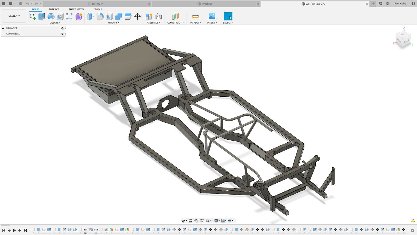
Well over many long winter evenings I managed to model up practically all of the AK chassis - and then spent a few more evenings remodelling some bits of it when it was apparent some of my measurements were not correct.

It's not fully complete - I still have to finish off the tubular bracing parts - but I've included a couple of pictures below.  I've added a sneak preview of part of the chassis with brake pipes and clips modelled - I'll cover this more fully in one of my posts on the fixing of the brake lines.  There's also a part-finished render from Fusion 360 of this section of the chassis (the processing power of my Mac isn't up to getting the full render done!) - let's see if it looks as good when I actually finish it!


Sunday 16 February 2020

Welding Practice

One of the main issues hampering my progress on Project Snake has been the state of my garage.  Never the tidiest person at the best of times, over the winter the garage has become a bit of a dumping ground.  I spent a couple of days having a very early spring clean which made things look a lot better.  However, I was still fed up of tripping over my welder(s) and gas bottles which always seemed to be in the way no matter where I put them.

Having added a TIG welder to the tool arsenal last year, I had decided that the disposable gas cylinders were a waste of money and invested in two Hobbyweld Plus size gas cylinders; a 5% C02: Argon mix for MIG welding and an Argon only cylinder for TIG welding.  

To tidy up the storage of the various welding paraphernalia and make it all a bit more portable (the MIG welder and gas cylinders are not exactly easy to handle) I decided to knock up a welding cart.  As well as freeing up some space I thought that it would also give me some good practice with the hot metal glue gun.

I produced a design for the cart in CAD and ordered the necessary lengths of steel section and plate.


CAD Design for Welding Cart

The bottom frame was made from 50x25 RHS while the rest of the frame was 25x25 SHS with 2mm Steel Plate for the shelves.  

Some various progress photos are shown below.  I think my MIG welding skills have improved somewhat after undertaking this project.  It is still very frustrating though, to lay down a series of really nice looking welds and think you've cracked this lark, to follow them up with the crappiest blobbiest bit of weld ever seen... Still, practice makes perfect.  Getting the torch angle right seems to be the key to getting a nice looking weld as well as a bit of a gap between the parts to be welded.


Steel for Bottom Tray cut and prepped
Looks nice - but a bit blobby...
Corner after welding and grinding
Bottom Tray complete
Steel for shelves cut and prepped
Shelf frame - various levels of weld quality...
Shelf top welded on
Using a gas cylinder to form Bottle bracket
Bottom bottle supports in place
Starting to take shape
Handle side cut and shaped...
...and end of handle notched to fit.
Upper bottle mount formed from 50x2mm steel strip
Tapping bottom tray for some casters
Heavy-duty casters - good for 200kg each!
Wheels and several coats of Hammerite Smooth

Have to say that I'm quite pleased with the final outcome.  A couple of bits need some fettling; the upper bottle stay doesn't quite tighten up with the bottles in place.  I also rushed the painting a bit, trying to beat Storm Ciara, and forgot to wipe all the grinding dust off the shelves before painting; this led to some vigorous sanding down and another two cans of Hammerite.  The finish is still not great but largely hidden by the welders, so it will do.

Cart loaded up...
...and ready for action

So that's tidied up some corner of the garage - time to get on with the rest of the Cobra build!!

Sunday 19 January 2020

Project Snake Update - Jan 2020

Happy New Year to everybody!

I have just realised that it is also just over a year ago that my AK body/chassis kit was delivered.  So it seems like a good point to take stock of where I have got to in the build process.

I also recently discovered that my kit delivery date of 11 January (2019) is the same date as Carroll Shelby's birthday (11 January 1923).  An interesting coincidence!

Delivery Day - 11 January 2019

As it currently stands, I have not made as much progress as I would have liked. The front suspension/axles are complete (minus brakes) but at the rear, I have only got as far as installing the differential.  I had hoped to be at rolling chassis stage by this time.

Front axle complete except for brakes

Rear Differential Unit in place

I have got a lot of the parts for the rear axle prepped and ready to install.  My decision to prep a lot of the parts myself (home sandblasting and powder-coating) took a lot longer than I anticipated (but hopefully saved me a bit of money and added to the satisfaction of doing as much as I can myself).

Rear axle components prepped and powder-coated ready for re-assembly

I have also not really had many opportunities to do much on the build since my last post back in October 2019.  Many things contributed to this.  Work went a bit mental back in the autumn and I spent quite a few weekends having to work rather than play!  We also had some work done on the house (which is still not fully finished), having most of the downstairs floors replaced.  This meant clearing out the contents of all the rooms and a lot of this stuff found its way into the garage, with the result that working space and access to anything was severely hampered.

Even when I did find some time (and make some working space) I found myself thwarted by some unforeseen issues.  I bought myself a 3HP compressor with a 100-litre receiver back in the summer; this performed faultlessly during all the sandblasting that I was doing at the time.  

New compressor - doesn't like the cold...

When I came to try and use the compressor in late autumn, it would not start.  There was a brief humming from the starter before it blew either the fuse in the plug or tripped out the garage power supply!  

I was worried that the starter capacitor was faulty. But after the usual extensive internet-based research, it seems that 3HP is right on the limit of what a domestic electricity supply can provide, especially if the plug is at the end of a long run of cable (such as a garage). Also during cold weather, the overall demand can affect the actual voltage supplied.  Additionally, as the temperature drops the viscosity of the oil in the compressor motor increases.  The result of these factors is that, in colder conditions, the compressor motor can not produce enough power to overcome the higher viscosity of the oil and effectively stalls (and blows the fuse).  

This can be overcome by heating the compressor oil (using a strategically applied heat gun) but took a long time (and spare fuses) before I managed to coax the compressor to turn over.  Hence not a practical solution for trying to do some quick jobs...

Time has not been wasted though.  I have been doing some planning of the next stages, including the brake and fuel line routing and fixing (no ordinary P-clips will be used in this build!) and I am also toying with the idea of utilising an electronic handbrake based on a 12V linear actuator.

Starting to mock-up handbrake set-up in CAD

The next list of jobs to do are:

  • Extract broken screws from one of the rear hubs;
  • Clean and powder-coat ABS rings from rear hubs (these hold the rear axle stub in place);
  • Reassemble rear hubs;
  • Install new universal joints in driveshafts;
  • Install hubs/driveshafts and rear wishbones;
  • Install rear shocks;
  • Cut down rear brake backing plates and powder-coat;
  • Install handbrake shoes and springs in hubs.

The other main development in the progress of Project Snake has been the engine.  My original plan was for a Chevy 6.2L LS3 motor.  This was going to be built by Kyle Rushall.  Kyle and I have been exchanging texts over the past few months about the exact specification of the motor I was after.  In the end, he offered me an alternative engine at a price that I couldn't really refuse.

I'm going to leave you all hanging for the moment as to the final spec, but it will be a 427 cubic inch engine (but not a Ford...), it has titanium con-rods and I need to find somewhere in the confines of the AK body/chassis to locate a dry-sump tank...

A titanium rod - 464 grams compared to over 600 grams for a steel rod

Kyle has started prepping the block and heads.  The engine build should commence around the end of January and is due for completion sometime in March 2020.

The downside is that the new engine is a "bit" more expensive than I had previously budgeted for so I need to rethink spending plans for the next stages while I save up!


Saturday 1 June 2019

Stoneleigh Kit Car Show - 2019

My son and I  took a quick trip up to Stoneleigh for the National Kit Car Show over the first May bank holiday weekend.

The last year seems to have zipped by; at last year's show we were still doing research before buying our cobra kit and now we are on the early stages of the build.

The show was much busier than last year and it was good to see the AK stand getting lots of visitors!

The main purpose of the visit was to get some thoughts and ideas around future details of the build; colours, dashboard layouts, lights, wheels etc etc.

Unfortunately the visit opened up some very clear differences between my son and I!  I am tending towards quick-lift jacks rather than over-riders, he is thinking full bumpers and over-riders.  I wanted a classic wooden steering wheel, he wants a modern black wheel.  I was thinking classic gauges in the cockpit, he found some horrible digital colour changing gauges (no way!).

It's a good job we have plenty of time before having to make some of these choices!!!!


Lights....modern?...

...or classic P700 style...?


Classic oxblood cockpit...

Nice grey leather cockpit...

Or black...?  (No wooden steering wheels in sight!!)

We also had a good wander through the trade stands and picked up some essentials including some abrasive disks, a new set of automatic wire-strippers, a new sign for the garage, some more powder-coating powder and a TIG welder.  OK the TIG welder wasn't an essential but I am a sucker for a bargain and it was a show special, half price at £100!


Retail therapy....

Of course the welder turned out to maybe not such a bargain after all and when I got it home and opened it up it has a strange blue plug on the end of the power lead.  Apparently they don't fit a standard 13A socket......and it requires a 32A supply.....and my garage only has a 16A supply.......

Oh well - time to call the electrician!!

Can't get that into a normal socket!!!


Saturday 20 April 2019

Christmas Holiday Projects - Powder Coating Stand


I have decided to try DIY powder coating the various donor parts that I will be re-using.  My plan is to buy the Eastwood Hotcoat Dual Voltage powder coat gun from Frost Restorations (although at time of writing it is still out of stock).

When watching the Eastwood powder coating guide on YouTube they used a cunning stand to clamp an oven shelf (with parts to be coated hung from the shelf) allowing easy transfer into the curing oven.


Powder Coating Stand - photo courtesy of Eastwood.com

Allows transfer of oven shelf and parts directly into
oven for curing - photo courtesy of Eastwood.com

I thought it was be a good project to try and make my own stand as it would allow me to brush up (learn!) on some of my metal working skills prior to using them in anger on the Cobra build.

I bought the main metal sections, 3 No 1m lengths of 25mm box section, a 1m length of 50mm by 3mm angle section and a 1m length of 25mm by 3mm plate from Ebay, some M8 roofing bolts from Toolstation and some M8 Thumbwheels and 25mm square inserts from Ross Castors.


Selection of steel sections

I used the proverbial back of a fag-packet to work out dimensions, angles and hole positions, testing my memory of trigonometry to the full!


Detailed Engineering Fabrication Drawing....

I cut the steel sections to the required lengths / angles using a Rage Evolution Mitre Saw.  I have used the saw many times previously for timber but this was the first time I had tested it out on metal.  Have to say it cut through the various steel sections very easily and with nice clean cuts.  Usual H&S rules apply - cutting metal does result in lots of tiny shards of metal being flung everywhere - wear eye protection and gloves (and I spent the next week picking small bits of metal out of my coat and jeans!!!).


Sections cut to length - starting to take shape!

One of the main reasons I decided to have a go at this project was so that I could have a go at MIG welding.  I bought a MIG welder years ago when I was thinking of attempting some body repairs on my Trans Am but never actually got round to using it!

I have a Siegen Mini-Mig 130 (which is a cheap Sealey brand).  Its quite a small output welder and does not have a fully adjustable power level (2 switches giving four power levels (Min I / Min II / Max I / Max II)).  As I bought it with the intention of only welding thin body panels I wasn't that bothered about a higher power machine at the time.


It was a bargain 10 years ago....

I did the obligatory self-learning MIG welding course by watching a number of videos on YouTube and feeling confident headed to the garage to set up the welder and hope, that after 10 years of gathering dust in my garage, it actually worked!

I had some old lengths of 5mm steel plate lurking in my garage and used a couple of these to practice laying down a decent weld bead.  Well the good news was that the welder worked.  The bad news is that welding is not as easy as it looks!  Lots of sparks and spatter but not a lot of weld!  Eventually I concluded that the lower power settings were a waste of time, and after a bit of twiddling with the wire speed control knob and experimenting with the angle of the welding torch I finally managed to produce something that looked like a reasonable bead of weld.  Time to start welding up my project!

I started by trying to weld an end cap on the bottom of one of the box sections. I cut a square section of plate and tack welded it in place.  So far so good.  However the first attempts to weld along the joins were disastrous.  The results were back to being blobby and splattery even though I had not changed the settings on the welder.


End cap tack welded in place

I thought I had solved the issue when I realised that I had run out of gas!  I was only using a small disposable Argon / CO2 gas cylinder and clearly my extensive test welding had exhausted the supply.  However even after buying a couple of new cylinders, I still could not get a decent weld; still blobby and grinding down the weld revealed holes and poor penetration.  


Not the best advert for welding...

I pressed on, welding and grinding and rewelding and regrinding until I was happy enough with the end result (which used another whole bottle of gas to weld on two end caps!!!!)


After extensive welding and grinding....

It was then that I realised that I had got a slight twist in the cable leading to the welding torch which was enough to cause the wire feed to be a bit erratic.  Once I untwisted the torch, weld quality suddenly improved - this is a relative statement, the results were far from what I would call good, but a definite improvement!  A lesson learned - keep the cable from the welder to the torch as straight as possible!

Next step was to drill the holes in the bottom of the main section, the bottom brace and the bottom legs so that I could get the position of the plates either side of the bottom brace in the correct place.  Using my precise engineering drawing (?!) I marked the hole locations with a metal scribe and centre punch.  I drilled 4mm pilot holes and then opened out to 6mm and then to 8mm.


Drilling....

Drilled....

Final steps were to weld two sections either side of the bottom brace, to weld up both of the bottom legs and the weld the angle section onto the top of the main leg.  Although my welding was still a little untidy, once ground down the joints all looked pretty solid.


Plates welded either side of bottom brace
Bottom Legs welded together

Almost looks like a stand!

I tack welded a couple of nuts onto the bottom brace and onto the top shelf bracket then gave everything a wipe down with white spirit and sprayed it all with 3 coats of Hammerite Smooth.

I am actually pretty chuffed with the result - looks just like it was supposed to (which is always a bonus!!) and the thumbwheels and end caps add a nice professional looking touch (just don't look too closely at the welding).