Showing posts with label Chassis. Show all posts

Friday, 13 September 2024

Handbrake - Part 2 - Installing a Linear Particle Accelerator

The normal handbrake set-up on the AK Cobra is a cable-operated system, utilising an XJS handbrake lever in the cockpit, operating a lever mounted above the differential unit that in turn pulls on the handbrake cables connected to each rear hub.

The original AK handbrake set-up, whereby the cable simply pulled directly on the actuator lever, did appear to have a reputation for not being very efficient (based on a read of several internet forums).  AK has addressed this and modified the set-up with the cable operating the lever via a pulley set-up to provide twice the pulling power.  Improved, but still a bit touch and go come IVA / MOT test time.

AK Handbrake Modification (from AK Build Manual)

I decided to make a couple of further modifications to the system myself to improve the handbrake performance.

The first modification involves the XJS handbrake lever.  I obtained the lever from Simply Performance at the same time as my donor axles.  The photos below show the lever before and after modification...

XJS Handbrake Lever before initial modification...

...and after modification!

The second modification involved the purchase of an electronic handbrake kit from Hollin Applications Ltd.  This kit was developed for the Motability market in the UK but seems to have gained popularity with many Cobra builders over recent years. The kit includes a linear actuator, an electronic controller and a simple switch.  The controller enables the pull / push force on the actuator to be adjusted up to a maximum of 800N or 80kg in old money.  It also meets the IVA requirement of preventing the handbrake from being released unless the ignition is switched on (it does also have the problem that the handbrake can't be released if the battery goes flat - but we will cross that bridge later).  The switch is a bit basic and will do for initial testing, but it will be replaced with something to match the other interior switchgear (when I decide what that will be...)

Linear Actuator

A bracket of some description is needed to mount the actuator to the rear chassis cross-member.  Since I made the decision to go with the Hollins kit, AK has actually started using them in their factory builds and has started selling an electronic handbrake kit including a mounting bracket.  However, I felt the price they were asking for the bracket alone was a bit steep and as I enjoy spending valuable time that I haven't got, making unnecessary bits for this build, I decided to make my own...

Fortunately, I got a bit of a headstart via Steve Sutton's build blog which referenced a solution by another builder Michael de Kok, who had included the details of the bracket he had fabricated for his own Cobra electronic handbrake install.  So, giving credit where it is due, I have borrowed the same design.

I completely forgot to take any photos of the fabrication process, so thankfully you can all just see the final bracket before and after powder coating!

Final bracket before coating (don't be too harsh on my welding)...

...and after powder coating

I fitted the handbrake actuator to the bracket using a long M6 bolt with a couple of spacers that I machined from some offcut of steel bar.

The actuator is installed into the bracket.

I then drilled and tapped some holes in the rear cross-member and fixed the bracket/actuator to the cross-member with some M8x1.25 bolts and spring washers.

The handbrake actuator & bracket are fixed to the rear cross-member.

I also needed to replace the operating lever from the item that AK supplied.  I fabricated a new lever from a 5mm thick steel plate with a small section of steel channel welded on the end.  The channel end needed to be reworked with some light grinder action to prevent the lever from fouling on the chassis at full throw.

New handbrake operating lever

I trial-assembled all the bits and wired up the control board temporarily to test out the operation.  Thankfully it all seemed to work OK with the actuator shutting down at extension once the load from the handbrake cables started coming on; the control box is preset from Hollins at 50kN load.


The final assembly involved powder-coating the operating lever, making up a couple of nylon spacer washers and bolting it all back together with copious amounts of copper grease.

Final handbrake assembly


Sunday, 10 March 2024

Couple of Minor Jobs - Part 2

I have finished off a load of small jobs that are not really worthy of a post all of their own.

The first was to add an earth strap between the engine and the chassis.  Just to be on the safe side I bought a 50mm2 earth cable (which should cope with 345 Amps), with a 10mm lug on each end from PCS Cables.  This was bolted into a convenient hole in the engine block at the nearside front.  I drilled and tapped a hole in the top of the chassis rail and ground off a bit of the powder coat to ensure a good contact.

Engine Earth Strap 

I also put the final hose finisher on the crankcase breather hose.  The hose finisher that I originally bought is still hiding in the garage somewhere, probably hanging out with a 10mm socket, and laughing at me.

Breather hoses completed!

I have given the front of the radiator a couple of coats of Eastwood Radiator paint in satin black.  The bare aluminium finish was not quite in keeping with the "stealth" look that I have in mind for the finished car.  I should have done this before I installed the radiator onto the chassis, but I managed to mask up most of the front with newspaper and a couple of old blankets to protect everything from any over-spray.

Radiator masked up prior to painting...

...and after painting and masking removed

I have also added oil to the rear differential and the gearbox as it is far easier to do this while access is good rather than leaving (or forgetting) until the body is on.

I bought 2 litres of Castrol Transmax oil which is specially formulated for limited slip differentials and used a funnel and a length of clear PVC tube to fill the differential with oil.  I managed to get almost all of the 2 litres into the differential before the oil started leaking back out of the filler oil.

Differential oil

Funnel and PVC pipe filling arrangement

For the gearbox, I bought 3 litres of Motul Dexron III oil which is the recommended fluid for the Tremec T56 transmission.  I used the same funnel/pipe setup to fill the transmission and again managed to get almost all of the 3 litres in before the oil started weeping out of the filler hole.

Transmission fluid

Filler hole for T56 transmission

I also have finally got around to welding up the various threaded bungs I have added to the chassis for the fuel tank, gearbox and exhaust mounts.  I treated myself to a day welding lesson at The Machine Shop to try and get the hang of TIG welding. I'm still not "stacking dimes" but at least I managed to master the art of getting a bit more heat and penetration into the welds.  As the body will sit on most of the locations of these bungs, I ground them down flush to the chassis rails and then treated them to a couple of coats of POR15 rust preventative paint.

Powdercoat ground off around area to be welded

A dodgy stack of dimes...

...after grinding welds down...

...and after two coats of POR15


Monday, 17 October 2022

Brake Lines Part 5 - Rear Brake Lines and Fittings

I've been putting off completing the rear brake lines as the run from the bracket on the chassis leg at the front of the car to the position of the 3-way connector at the back of the car is rather complicated; not only does it have to follow the bends of the chassis along the transmission/prop shaft tunnel, but it also needs to partially run along the top of the chassis rail and then drop down to continue along the side of the rail.  It's also a single length of pipe of around 1.9m that needs 8 bends put into it accurately so that it fits into the front union and rear 3-way connector.

The other factor was my desire to use my over-engineered brake clips to secure the pipe run and try to come up with locations where these could be installed and maintain fixing centres of less than 300mm.  There is a cut-out in the chassis rail to give clearance to the starter motor which is greater than 300mm.  I was originally thinking to run the pipe down this recess and secure with a clip on the sloping face so that I could achieve the required fixing distances; I went and had a look at Richard Chippendale's build once he had got his engine installed and I am sure there was enough space.  However, as time moved on, I became less confident that this would work (the recess is there for a reason, right?).

My original thought for routing the rear line (in red)

In the end, I concluded that I was going to have to stick with the tried and tested AK routing for the rear brake line and would have to suck up using some P-clips or similar to secure the pipe run along the top section of the chassis rail.

I also decided not to bother with my previous CAD model approach for determining the lengths/bends in the pipe run; with the number of bends and changes of direction (and my limited CAD design abilities) modelling the pipe was just going to take too much time.

Time for PAD (Plywood Aided Design)!

I clamped a piece of 600x1220 plywood to the underside of the chassis and traced the outline of the chassis rails onto the wood.  I could then offset a line, representing the centre of my brake clips, and draw out the line of the pipe run in a handy 1:1 scale!

Time for some Plywood Aided Design...

With some additional 1:1 sketches for the bends down the chassis rail, I was able to measure the length between all the bend vertices and calculate the overall length of the pipe required and the position of my marks for bending.

I cut an over-long section of 3/16" brake pipe and started with the flat bends in the middle of the pipe run, along the transmission tunnel.  This section was bent up and secured in place on my plywood template using some push-in plastic clips.  This helped secure the pipe in place so I could make sure I got the correct orientation of the next bend.

A perfect fit!

I also remembered to put the brake fitting on the rear end of the pipe prior to forming the brake flare!  

Next, I made up the short section of straight pipe at the offside rear, from the flexible brake pipe to the 3-way connector at the rear.  This was a dead straight piece of pipe with the dimensions measured from my 1:1 sketch so what could go wrong?  I don't know what I did but I clearly measured something wrong, such that the first attempt was too short by a country mile!  The second attempt was much better.

Perfect - at the second attempt...

I then installed this section of the pipe and the 3-way union which allowed me to hold the rear of the long rear pipe run in place.  I could then check and double-check the location and measurements for the pipe bends up and over onto the top of the chassis leg before tentatively forming the bends.

Pipe run held in place temporarily and bend over the chassis formed

Where the pipe runs along the top of the chassis rail adjacent to the starter motor cut-out/recess I have elected to use some plastic push-in pipe clips from Car Builder Solutions; these have a small plastic collar, which is inserted into a 6mm diameter hole, the clip then pushes into the collar and clips into place.

Non-over-engineered Plastic Pipe Clip

The next task was to bend the pipe back around to meet up with the union on the front chassis leg.  Again I was sure to install the pipe fitting prior to forming the flare on the end of the pipe and making the bend.

The last couple of bends and everything lined up perfectly!

The last pipe-bending operation was to form the section of pipe from the 3-way connector that passes over the top of the differential nose and joins to the nearside flexible brake pipe.  I had modelled this section of pipe in CAD so was able to print out a sketch with all the necessary dimensions to enable me to accurately bend this into shape.

Last section of pipe bent up and in place

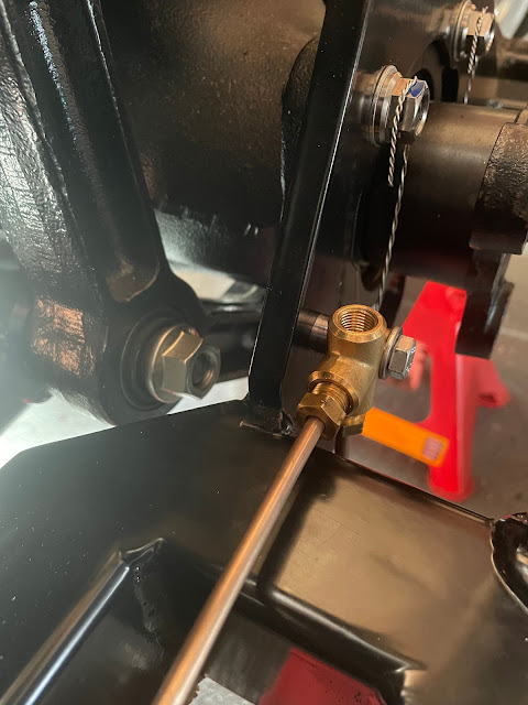
With all bending done I could fix the long run in place with five of my bespoke brake clips (which will also be used to hold the fuel return line to the tank in place).  This fixed the position of the 3-way brake union and using a transfer punch I could locate the centre of the fixing hole on the plate across the rear of the AK chassis.  

Unfortunately, the centre point of this hole was not ideal from a drilling and tapping perspective.  The tubular stiffening cage of the AK Gen III chassis provides enough of an obstruction to prevent being able to use a normal drill.  I had already discovered the need to purchase a 90-degree drill to be able to drill the holes to fix the brake clips along the inner legs of the chassis so this was pressed into action again to drill a 6mm hole.  

However, when it came to try and tap the hole for an M7x1.0 thread it was impossible to rotate the tapping wrench sufficiently to get the tap to start to bite in the hole.  I had to start the tap with a pair of pliers and then do my best with an adjustable wrench to continue trying to tap the hole.  It got to the point where I couldn't turn the tap anymore for fear of snapping it and so I couldn't tap the hole to the full depth.  Thankfully I managed to get enough thread cut so that I just needed a washer under the head of the bolt to get the union tight up against a spacer and all the pipes lined up where they should be.

3-way Brake Union fixed snugly in place

The last job was to drill a couple of holes to insert some plastic brake clips to secure the pipe over the top of the differential nose.  Again this job required the use of the 90-degree drill and several 6mm drill bits and I managed to snap one of the bits whilst drilling the second hole; this left a ragged hole which simply blunted any drill bit which I attempted to use to subsequently complete the hole.  In the end, I had to give up and drill a new hole just to the side of my original attempt.  

Pipe over differential clipped in place

I will, at some point soon, remove all the brake lines, blow them through with compressed air to make sure all detritus is removed and then fully tighten up all the unions for the last time.  I will also put some thread lock on the bolts securing my custom brake clips to the chassis for added peace of mind.

But for the moment the brake lines are done!


Wednesday, 28 September 2022

Brakes - Part 3 - Rear

 The rear calipers supplied AK Big Brake upgrade kit usually are designed to work with 295mm diameter by 10mm thick rear discs (non-vented).  As my donor car came with 305mm diameter by 20mm thick vented discs I was keen to retain this setup.  Fortunately, HiSpec (who make the upgrade kits for AK) were able to adapt the spacer between the two halves of the caliper to accommodate my larger and thicker discs.

As at the front, the new rear calipers are larger than the original donor single-pot items but weigh in at 1.7kg compared to the 2.06kg of the originals.  They also benefit from two pistons per side to improve the application of braking pressure to the pads.

Size comparison - original caliper looks very sad in comparison

2 pistons per side compared to the single piston original

New Ferodo pads (left) are similar in size to the originals

I ordered some new rear discs from EBC brakes.  I went with their USR Sports Series disks which are slotted and come in a black thermic coating to help combat corrosion.

As with the front calipers, the kit comes with new brackets and bolts to fix onto the rear hubs onto which the callipers are attached.  I fitted these and torqued the mounting bolts to 60Nm/44lbf-ft.  

New caliper mounting blocks and bolts - with confirmation that they have been adapted for 305 x 20mm discs

I inserted the brake pads before installing the calipers - again this could be done with the caliper on the car but I figured it would be easier to do it on the bench (or floor as it turned out).  For the rear pads, the kit comes with some springs which need to be slid onto the outer edge of the pads.  I remembered to give the back of the pads a smear of copper grease before inserting them into place.  They are secured by two pins held in place with R-clips, the springs on the pads need to be eased under the pins as they are inserted to hold the pads into place.

Brake pad spring installed on the outer edge of pad...

...and a smear of copper grease added to the rear of pad...

...before pads inserted into caliper and held in place with retaining pins.

The last task before the final installation of the calipers was to adjust the handbrake adjusters on both sides so that the handbrake pads were just rubbing on the inside of the discs (although I think some further adjustment may be required at a later date). I could then bolt the calipers to the mounting blocks and torque the bolts up to 60Nm/44lbf-ft.  

Rear brake discs and calipers done!

And with that, I have probably reached the stage of the build that I was originally hoping to get to at the end of 2019...so only 3 years behind schedule!

Tuesday, 27 September 2022

Rear Axle Reassembly - Part 11 - Finally completed

Once my new half shaft spacers had arrived I could get on and (hopefully) complete the rear axle assembly.

Upon removing the spacers from the packaging, I was disappointed to find that they were both made from steel, and not some more exotic metal, as the price I paid for them might have suggested.

Could a golden spacer lie within...No!

I installed both spacers (4mm on offside / 7mm on nearside) and a single rear camber shim on each side initially.  It actually turned out that I needed just the single 4mm spacer on the offside and the 7mm spacer plus two shims on the nearside to get a camber setting of 0.3 degrees negative on both sides.

Spacer in place on differential output flange

Oh look - those shims do fit after all...


0.3 degrees negative on that side...

...and 0.3 degrees negative on the other side.  Job done!

With that done, I could remove all the 7/16" nuts from the half shafts for the last time and replace them with 7/16" Nylocs.  These were torqued up to 90Nm / 66lbf ft.

The next job was to remove the original drive nuts from the hub end of the half shafts and replace them with new items.  The Jaguar service manual recommends that the splined end of the half shaft within the rear hub is covered in thread lock over 30-50% of the radial area.  I used Loctite 270 and covered the rear part of the splined section before reassembly.  As well as a new drive nut I also replaced the conical washer with a new item.  

Today's thread lock is Loctite 270...

...applied over the rear of the splined section

New conical washer and drive nut (note the red insert)

The drive nuts need to be tightened up to a whopping 225lbf ft / 305Nm of torque.  I tightened them up initially using my air spanner.  I then used a large pry bar against the wheel studs and braced against the floor to stop the hub from rotating and dug out the largest of the torque wrenches from my tool arsenal.

Top tip - push the wrench down rather than trying to pull it up or side on otherwise you may end up pulling the chassis off the axle stands.  Also, try and position yourself away from the pry bar.  Mine ended up bending like a banana and if it were to break free from the wheel studs, it will cause serious damage!

Drive nut installed and tightened to ridiculous torque level!

The last step was to install the rear shock absorbers.  These are fitted in place with 7/16" x 4.5" bolts, M12 washers and 7/16" Nylocs in the top mounts and 7/16" x 2.5" bolts, M12 washers and 7/16" Nylocs in the bottom mounts.  AK only appear to supply a single M12 washer per bolt so I splashed out and added an extra washer to have one under the bolt head and one under the nut on all mounts.

Shiney new shock absorber - fitted so adjuster knob is at the bottom and facing inboard.

Mounting bolts - these were given a liberal smear of copper grease before installation

Rear Shock Absorber installed

The final step was to torque down the shock absorber mounting bolts to 38Nm (28 lbf ft) for the upper mounts and 64Nm (47lbf ft) for the lower mounts.  And that is the rear axle finally completed!