Saturday 20 April 2019

Christmas Holiday Projects - Powder Coating Stand


I have decided to try DIY powder coating the various donor parts that I will be re-using.  My plan is to buy the Eastwood Hotcoat Dual Voltage powder coat gun from Frost Restorations (although at time of writing it is still out of stock).

When watching the Eastwood powder coating guide on YouTube they used a cunning stand to clamp an oven shelf (with parts to be coated hung from the shelf) allowing easy transfer into the curing oven.


Powder Coating Stand - photo courtesy of Eastwood.com

Allows transfer of oven shelf and parts directly into
oven for curing - photo courtesy of Eastwood.com

I thought it was be a good project to try and make my own stand as it would allow me to brush up (learn!) on some of my metal working skills prior to using them in anger on the Cobra build.

I bought the main metal sections, 3 No 1m lengths of 25mm box section, a 1m length of 50mm by 3mm angle section and a 1m length of 25mm by 3mm plate from Ebay, some M8 roofing bolts from Toolstation and some M8 Thumbwheels and 25mm square inserts from Ross Castors.


Selection of steel sections

I used the proverbial back of a fag-packet to work out dimensions, angles and hole positions, testing my memory of trigonometry to the full!


Detailed Engineering Fabrication Drawing....

I cut the steel sections to the required lengths / angles using a Rage Evolution Mitre Saw.  I have used the saw many times previously for timber but this was the first time I had tested it out on metal.  Have to say it cut through the various steel sections very easily and with nice clean cuts.  Usual H&S rules apply - cutting metal does result in lots of tiny shards of metal being flung everywhere - wear eye protection and gloves (and I spent the next week picking small bits of metal out of my coat and jeans!!!).


Sections cut to length - starting to take shape!

One of the main reasons I decided to have a go at this project was so that I could have a go at MIG welding.  I bought a MIG welder years ago when I was thinking of attempting some body repairs on my Trans Am but never actually got round to using it!

I have a Siegen Mini-Mig 130 (which is a cheap Sealey brand).  Its quite a small output welder and does not have a fully adjustable power level (2 switches giving four power levels (Min I / Min II / Max I / Max II)).  As I bought it with the intention of only welding thin body panels I wasn't that bothered about a higher power machine at the time.


It was a bargain 10 years ago....

I did the obligatory self-learning MIG welding course by watching a number of videos on YouTube and feeling confident headed to the garage to set up the welder and hope, that after 10 years of gathering dust in my garage, it actually worked!

I had some old lengths of 5mm steel plate lurking in my garage and used a couple of these to practice laying down a decent weld bead.  Well the good news was that the welder worked.  The bad news is that welding is not as easy as it looks!  Lots of sparks and spatter but not a lot of weld!  Eventually I concluded that the lower power settings were a waste of time, and after a bit of twiddling with the wire speed control knob and experimenting with the angle of the welding torch I finally managed to produce something that looked like a reasonable bead of weld.  Time to start welding up my project!

I started by trying to weld an end cap on the bottom of one of the box sections. I cut a square section of plate and tack welded it in place.  So far so good.  However the first attempts to weld along the joins were disastrous.  The results were back to being blobby and splattery even though I had not changed the settings on the welder.


End cap tack welded in place

I thought I had solved the issue when I realised that I had run out of gas!  I was only using a small disposable Argon / CO2 gas cylinder and clearly my extensive test welding had exhausted the supply.  However even after buying a couple of new cylinders, I still could not get a decent weld; still blobby and grinding down the weld revealed holes and poor penetration.  


Not the best advert for welding...

I pressed on, welding and grinding and rewelding and regrinding until I was happy enough with the end result (which used another whole bottle of gas to weld on two end caps!!!!)


After extensive welding and grinding....

It was then that I realised that I had got a slight twist in the cable leading to the welding torch which was enough to cause the wire feed to be a bit erratic.  Once I untwisted the torch, weld quality suddenly improved - this is a relative statement, the results were far from what I would call good, but a definite improvement!  A lesson learned - keep the cable from the welder to the torch as straight as possible!

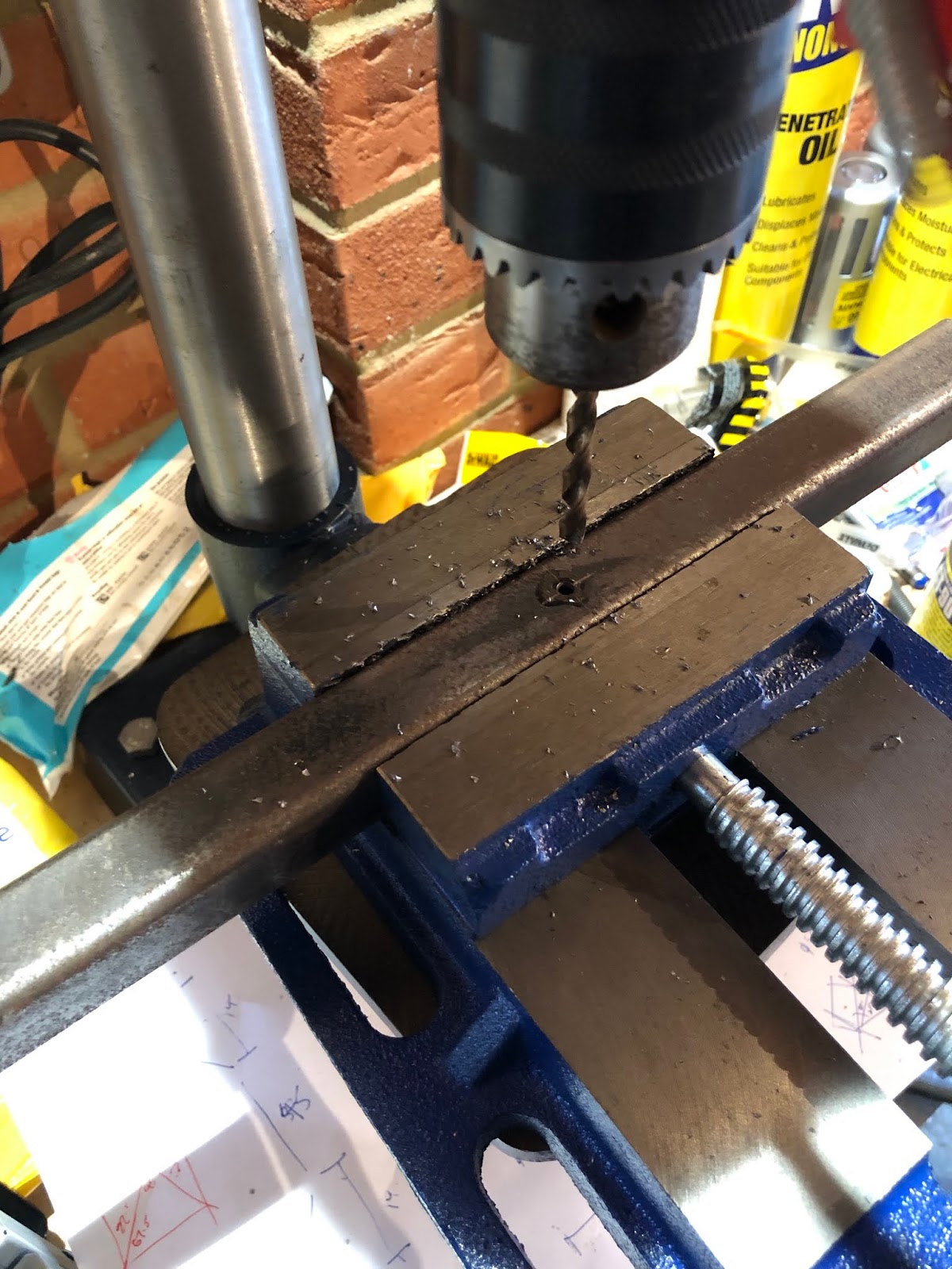
Next step was to drill the holes in the bottom of the main section, the bottom brace and the bottom legs so that I could get the position of the plates either side of the bottom brace in the correct place.  Using my precise engineering drawing (?!) I marked the hole locations with a metal scribe and centre punch.  I drilled 4mm pilot holes and then opened out to 6mm and then to 8mm.


Drilling....

Drilled....

Final steps were to weld two sections either side of the bottom brace, to weld up both of the bottom legs and the weld the angle section onto the top of the main leg.  Although my welding was still a little untidy, once ground down the joints all looked pretty solid.


Plates welded either side of bottom brace
Bottom Legs welded together

Almost looks like a stand!

I tack welded a couple of nuts onto the bottom brace and onto the top shelf bracket then gave everything a wipe down with white spirit and sprayed it all with 3 coats of Hammerite Smooth.

I am actually pretty chuffed with the result - looks just like it was supposed to (which is always a bonus!!) and the thumbwheels and end caps add a nice professional looking touch (just don't look too closely at the welding).


Paint or Powdercoat?

Since I bought the donor axles for this project I have been mulling over whether to just paint the refurbished parts or whether to get them powder coated for a more durable finish.

To me this project is about doing as much as I can myself during the build process, learning as much about how to do it all, and being able to say at the end "I did all that!".  

So in that regard painting seemed the obvious choice.  Powder coating requires specialist equipment and large curing ovens; well beyond the scope of the average DIY car builder.

Well maybe not......

Over the many years that I have been attending car shows, I've often walked past a small stand promoting a home powder coating system.  I've stood and watched the demonstrations as the guys on the stand powder coat small squares of metal and then cure them using a hot air gun or an Infra Red heat lamp.  And I've always walked away thinking "what a load of...."

These stands were run by a company called electrostaticMAGIC (which is quite ironic as the company that AK use to powder coat their chassis and parts is called Electrostatic Magic Ltd......) and I actually need to offer these guys a huge apology.

In this internet powered age, I managed to find several very positive reviews of their product.  They have a blog on their website and on that, one of their customers had built their own curing oven using an Ikea filing cabinet and two Lidl hot air guns!

While scanning YouTube looking for reviews of the electrostaticMagic system I found a video by Eastwood covering their home powder coat system, which included a full demonstration of their dual voltage system.  This uses a lower voltage to charge the workpiece, together with a diffuser on the end of the gun, to provide better coverage and adhesion of the powder to intricate parts.  What was more interesting though was that they used a small table top oven to cure the parts which looked just like a normal small oven freely available on Amazon and eBay.

So maybe home powder coating could be a realistic option after all, at least for smaller parts.

It didn't take me long to decide to give powder coating a go! I decided to go with the Eastwood system over the electrostaticMAGIC version because of the dual voltage option. 

The Eastwood system is distributed in the UK by Frost Restoration, who sell all sorts of interesting tools, equipment and products for the auto restoration enthusiast.  Unfortunately having made the decision to go with the Eastwood option, Frost did not have any in stock and were not expecting any to be imported until early 2019!!  So I was just going to have to wait, which wasn't really a problem as, at that time, I was not ready to start painting / coating donor parts in any case.

Besides the wait gave me time to scour eBay, Gumtree and Marketplace for a suitable small oven.  This also took a fair amount of time to find one that was of the right size and at the right price, but eventually I picked up a 27 litre VonShef oven for the grand sum of £25!


Powder coating oven - I can also do my dinner in the garage now....

The guys at Frost Restoration had promised to give me a call as soon as they got the Eastwood system back in stock and, true to their word, I got a call from them towards the end of January and immediately ordered an Eastwood Hot Coat Dual-Voltage Powder Coating Gun Starter Kit.  The starter kit comes with 250g of gloss black powder, some high temperature masking tape (although I bought some extra rolls in various widths off Amazon), a variety of silicon plugs for masking holes / threads, some stainless steel hanging wire and some spare bottles for storing powder.  I also bought some Eastwood Pre-Prep (to remove grease prior to coating) from Frost and some tack-cloths from Amazon to ensure a nice clean surface prior to coating.


Ready to go powder coating!!

Unfortunately Frost don't sell the full range of Eastwood powders and only have a very limited range of basic colours.  However electrostaticMAGIC have a wide range of colours including metallic, candies, translucent and clear coats and even a chrome effect powder.  I will probably have a go with some of the metallic colours at some point in the future but for now just settled for 500g of Satin Black (to match my AK chassis).

So now I need to finish getting all the donor parts cleaned, stripped and prepped for coating.  Will let you know how it all goes!!

Steering Part 1 - Installing Steering Rack

The next task I tackled was the installation of the new AK power steering rack.

Again this should have been fairly straightforward - offer rack up to chassis, install nuts and bolts (M10 by 70 bolts, M10 washers and M10 Nylocs - not supplied by AK) and job done!?

AK make the point in the build manual to check that the pipes on the new rack do not foul on the chassis.  I was already aware from Richard's build progress that he had run into problems with this and I therefore was betting I would have the same issue.

True enough when I did the initial trial fit, one of the the two pipes on the rack was touching on the end of the off-side chassis rail.

Initial Trial Fit of Steering Rack....

....showed fouling of pipe on end of chassis rail

Another consultation with AK followed - Jon didn't see this to be an issue as the rack is solidly fixed to the chassis and can't move.  While this may be true I was still concerned that while the rack and chassis might not move relative to one another, vibrations transmitted through the chassis might still cause some slight rubbing of the pipe on the edge of the chassis rail which could eventually lead to failure of the pipe.  So I decided to try and get some suitable clearance between pipe and chassis.

I tried loosening the offending pipe to see if it could be moved slightly forward to provide some clearance - but that didn't work.  I also removed the pipe entirely to see if I could alter the bend slightly to provide clearance.  While this did look possible I was concerned that this might alter the length between the pipe unions and put some stress on the bends at each end.

In the end my fix was rather simple.  I wrapped a piece of spare 3mm steel strip in a towel to protect chassis and pipe, placed it on the end of the offending chassis rail, placed the rack into position and then fully tightened up the bolts.  The act of tightening the bolts, caused the steel spacer to push the pipe back out of way and provided a suitable amount of clearance.

Clearance granted!

I then did a final installation of the M10 securing bolts, with some thread lock on the nut end for good measure.

The ball joints are then screwed onto each end of the rack - the AK Build Manual recommends 14 full rotations of each ball joint as an initial setting.  You then need to measure between the centre of each of the ball joint studs and make adjustments as necessary (making sure to adjust both ball joints the same amount) to achieve a measurement of 47.5" between studs.

The ball joints are then secured to the uprights with M14 Nyloc Nuts (supplied) although I have not fully tightening these at present a) because I think I will add an M14 washer under the nut and b) I will leave final tightening until I have checked and set toe angles at some point in the future.

Steering Rack Installed

Front Axle Part 4 - It’s a Shocker

With the caster angles set, and new lower front wishbone shafts delivered, the next task was to carry out the final reassembly of the front suspension and install the front shock absorbers.

This was a simple matter of removing each of the wishbone shafts in turn, being very careful not to dislodge the wishbone and washers.  I then stuffed a goodly amount of copper grease into the front end of each wishbone and applied an equally liberal coating of copper grease to each of the wishbone shafts.  I then re-installed the shafts, which pushed the plug of copper grease through to the rear of each wishbone (hopefully aiding to ensure the full length of the wishbone and chassis tube is greased up).  The excess grease was removed with a wad of paper towel.

Copper Grease "Plug" at front of Wishbone
A generously lubricated shaft.....(minds out of the gutter please....)

For the lower wishbone shafts, I purchased some additional M22 washers from Westfield Fasteners to put under the bolt head to accommodate for the slight extra length of the shaft.  I also wasn't happy with the way the M14 castellated nut sat on the end of the inner sleeve of the lower wishbone bushing, so I also bought some extra M14 washers for the nut end of the shaft.

With all four shafts, greased, reinstalled and nuts tightened up hand tight, it was time to install the front shock absorbers.

As it seems to be with this Cobra building adventure, not all tasks are as simple as they should be.  I started by test fitting the 7/16" by 2.5" front shock bolts (supplied by AK) in each of the holes.  All were fine, except for the nearside lower shock mounting, which would not pass through the bushing which is pre-installed in the lower wishbone.  Closer inspection revealed that the inner sleeve of the bushing was slightly out of round at the front (the end was also a bit ragged which I was not altogether happy with either).

Slightly flattened lower shock mounting bushing

I decided to try and ream the inner bushing out with an 11mm drill bit, which appeared to be a great idea, until about the last mm of travel on the bit, which caught on the end of the inner sleeve and tore it out of the rubber completely!

B*gger......!

Unintentionally Disassembled Front Shock Bushing...

However this unintended action did reveal that the inner sleeve did not look in very good shape at all; not only was the front edge all ragged but it looked a bit distorted / crushed in the middle.  

A quick email to AK and Jon offered to press in a new bushing for me - this did mean that I had to remove my newly installed lower wishbone from the chassis, but that's why I hadn't fully tightened up any of the nuts yet wasn't it?

A quick trip up to AK, a cup of tea and a chat with Jon later, and I was returning home with a new bushing installed.

New (better looking) lower shock bushing courtesy of AK

Then it was a simple matter of applying copper grease liberally to the bushings and the shock mounting bolts and installing shocks on both sides.

Off-side front Shock installed

Final job was to tighten up all the bolts to the recommended torque settings (as per the Haynes Manual for the Jaguar XJ40).  For information, these are as follows:


I was unable to get a socket and my torque wrench onto the lower balljoint stud nuts, so I just tightened these as much as I could by hand using a spanner.  

Also with the lower wishbone pivot nuts, I ended up torquing these to around the correct value but then had to back them off slightly to be able to fit the split pin through the castellated nut and hole in the shaft.

Lower Front Wishbone Shaft - Retaining Pin inserted and secured

I also found when tightening the upper shock bolts that the bolt head was starting to cause the powerboat underneath it to crack slightly.  AK only provide a single washer per bolt (which I had put on the nut end) so I bought some additional 7/16" washers for the bolt ends and re-installed and re-torqued bolts to specification.

As each bolt is torqued down, I consider it good practice to mark it in some way.  I did this using a small blob of nail varnish on the bolt and nut.  I spent many happy hours in the local chemist perusing the shades before I settled on Danny Boy Blue.....


Other shades are available....


IMPORTANT NOTE

I have not been carrying out the assembly of the front suspension in exactly the same order as the AK build manual, mainly because I am not yet ready to install the front hubs and I have yet to refurbish my front brake callipers.

This does mean that I missed out a key stage prior to installing the shock absorbers which is to set the front camber angles (i.e the angle between the vertical axis and the steering axis when viewed from the front of the car).  The AK Gen III wishbone have elongated holes in the upper wishbone ball joint mounting for this adjustment.  However the camber is measured by checking the vertical angle of the brake disk with the wishbones set horizontally.

Now I had remembered that I needed to set the camber angle, hence I have not yet fully tightened the upper ball joint mounting bolts.  However, in order to get the wishbones horizontal when I get round to installing the brake disks, I will have to undo and remove the shock absorbers again......

Now its starting to look like a proper car!!!!

Front Axle Part 3 - Keeping a Level Head

Having initially assembled the front wishbones and stub axles, the next step is to check the caster angles on the uprights and adjust if necessary by redistributing the washers between the wishbones and the chassis.

Technical bit - the caster angle (as opposed to the camber angle) is the angular displacement of the steering axis from the vertical, the purpose of which is to provide a degrees of self-centreing for the steering.

Before checking the caster angles, the first step is to level up the chassis and the wishbones.

My garage floor is far from flat, level or even, so this apparently simple exercise took a fair amount of time.

The wishbones need to be horizontal for this step.  Expecting to to have to do some redistribution of washers I did not fully tighten the wishbone bolts.  This meant that I needed to support the wishbones on a another couple of axle stands.  

Then I checked the chassis was level side to side, by placing a spirit level across the chassis rails at the front.  

Wishbones supported - checking level across chassis

My chassis is supported on axle stands with some off-cuts of carpet between the axle stand and the chassis to protect the powder coat.  To get chassis level I jacked up the chassis and placed additional strips of carpet and / or thick corrugated cardboard on the axle stand to get everything levelled up.

I then placed a level on the top of the wishbones (you can just see the smaller level on the left hand wishbone in the photo above) and levelled the chassis front to back in a similar manner (whilst trying to maintain the level side to side...)

With that all sorted I carried out a final check on the level of the rear crossmember.  I didn't need a spirit level to see that this was far from level - in fact it was about 10mm off across the whole length!!

I couldn't believe that the AK chassis would not be level - so I double checked all the levels again (with both my large and small spirit levels) and deduced that one of my spirit levels (if not both) were not reading accurately.

My iPhone is equipped with a measuring and level app; I have tried the measuring app and found it to be bobbins and didn't expect the level app to be any better (and besides it reads in whole angles only).  So I downloaded the Angle Pro app which does give a reading to a 1/10th of a degree.

In order to check the Angle Pro app was working I also decided to buy a digital level from Amazon (ignoring my previous warning to check that what you are buying is the same as the picture - I received the world's smallest digital level by next day delivery....)

Then using a combination of spirit levels, iPhone Apps and the world's smallest digital level, I started the process all over again.


Level Front Crossmember - CHECK!
Level Rear Crossmember - CHECK!
Wishbone Horizontal - CHECK!! (it was also level front to back)

Time to check the caster angles.  

AK recommend a caster angle of between 6 and 8 degrees (with the aim that both sides are the same!).  AK provide a paper  gauge for this purpose; although the print quality is not great and it does rely on ensuring that a) the edge is actually parallel to the zero line on the gauge and b) the plumb line is fixed exactly at the intersection line of all the angle marks.

AK Caster Gauge in action (Photo courtesy of AK Sportscars)

I wasn't convinced that this was going to give a particularly accurate result so I decided to use digital methods!

The caster angle is measured by butting the gauge / level up against the two M6 screws previously installed into each upright.  The angle is then adjusted by redistributing the various washers on the upper and lower wishbones between the front and rear to alter the inclination of the upright.

The initial AK recommendations for distribution of the various washers proved pretty close in my case and I only had to move two washers from the front of the off-side upper wishbone to the rear to get readings on both sides of 6.7 degrees.  

6.7 Degrees on off-side upright...

...and 6.7 degrees on the near-side upright.  Result!

Now I can get on with the final assembly of the front wishbones and install front shocks.

Sunday 7 April 2019

Front Axle Part 2 - Getting Shafted...

As mentioned in my Front Axle Part 1 post, since my donor lower front wishbone pivot shafts had some minor scoring on them, I had decided to replace them with new shafts.

Scoring on existing Lower Wishbone Shaft

I originally ordered replacement shafts / castellated nuts (Part Number JLM11858) from SNG Barratt.  At the time of ordering these parts were on back-order with a 1-2 week delivery period.

Well after 2 weeks and no sign of my replacement shafts, I gave SNG a call.  They were very apologetic and advised that the parts needed to be supplied by the manufacturer and currently they were unable to provide a delivery date.  Since I really needed these shafts to progress with the build of the front end, I decided to cancel the order and look elsewhere.

Browsing through the internet sites of most of the well known Jag parts suppliers, these shafts appeared to be on 1-2 week lead time with them all and so I assumed I would have the same issue as I had experienced with SNG.

A fellow AK builder, Barry Boughton, who had got in touch with me after reading my blog, had mentioned a company called British Parts UK as a good source of parts.  Having checked their website, they did indeed have the parts and were showing them as in stock.  Rather than ordering over the web and then finding out that these were also on back order, I decided to give them a call.  They confirmed that, yes the shafts were in stock and that they could be delivered in 1-2 days, so I placed my order over the phone.  Job done!

Ok - perhaps not.  

3 days later there was no sign of any shaft delivery and even more strangely to my mind, no email confirmation of my order or delivery.  I gave it a couple more days to be sure, but with still no sign, I gave British Parts a call.  Well thankfully they did have a record of my order, but it transpired that although their system was showing the shafts in stock, when they had gone to the bin in the warehouse it was empty.  The shafts were on back order but the manufacturer was currently unable to advise on a delivery date (obviously the same manufacturer that SNG use...).  I'm not sure when British Parts were actually going to inform me of this, but being less than impressed, I cancelled my order with them.

I was running out of options and getting desperate to press on with the front suspension build.  My final resort was eBay.  Now I'm always very dubious about buying certain items on this well known auction website; many things are obviously low quality, fake, dubious origin, dodgy location etc etc and as these shafts are a major component in the front suspension of what will be a very high powered car, I did not want some inferior quality, cheap, reproduction items.

Having entered the part number into the eBay search box, the required items popped up as being available by seller called E-Type Parts.  All the feedback seemed very positive (and I was even more reassured by the fact that E-Type parts actually has their own website and are based in the UK, in Hull).  So taking a deep breath I ordered two shafts and the corresponding castellated nuts (Part No NL609401J).

Two days later I received a parcel containing two lower wishbone shafts and two castellated nuts.  Success!

Unfortunately not quite....

The supplied nuts did not fit onto the threaded ends of the shafts.  However Jonathan from E-Type Parts was very quick to offer a full refund on the nuts (he was surprised as he also thought that the NL609401J nuts, which are a 9/16 thread, were the correct ones for the shafts).  Between us we concluded that the shafts must have a metric thread, which I managed to confirm by checking with an M14 nut that I had in the AK nut and bolt pack. 

So now I needed to track down two M14 castellated nuts (the nuts are secured to the lower shafts with split pins).  Again not so straightforward as metric castellated nuts don't seem to be that common, but eventually I found a company called Westfield Fasteners who had the offending items for sale and an order was placed.

So now I have the new lower wishbone pivot shafts and nuts, I can get on with the front suspension build-up.

The shafts from E-Type Parts are slightly different to the original donor shafts; aside from the M14 thread instead of the 9/16 thread.  They are also very slightly a different length (longer), which might need some additional washers to accommodate, and the shoulder between the shaft and threaded portion is not chamfered, as on the original shaft, which does make it slightly more difficult to fiddle the shaft into place, through the various bushes and washers on the wishbone assembly.

New Lower Wishbone Shaft (top) vs original donor part (bottom)


Front Axle Part 1 - Wishbone Assembly

Having spent ages cleaning, stripping and prepping bits, it felt like a major step forward to start contemplating actually beginning to build up the new chassis, starting with the front suspension.

First on the list was to purchase some new service parts; I ordered the following from SNG Barratt.


Service parts - not a lot to show for 300 quid!


The donor vehicle top and bottom wishbone shafts both had some slight scoring on them so I decided to replace with new parts.  SNG had the top shafts in stock but the lower shafts are a special item and were on 1-2 weeks back order.

Having read through the AK Build Manual a few times, assembly of the front suspension looked quite straightforward and I was looking forward to some rapid progress......

Yeah right!

The first issue was that my replacement upper wishbone shafts didn't pass through the tubes in the AK chassis.  Not a massive problem, just required some fettling with a round file to remove some excess powdercoat and open out the tubes very slightly.

Next step was to fix the upper ball joints to the AK upper wishbones.  The ball joints sit in a recess in the wishbone and are fixed in place with M10x75 bolts and secured with M10 Nyloc nuts.  

Parts for upper wishbone

I found that there was quite a bit of play between the wishbone housing and the balljoints so I added another M10 washer in-between the two to take up the slack.  The M10 bolts were then tightened enough just to cinch the balljoint housing onto the balljoint itself and stop any movement.  The AK Gen III wishbones have elongated holes to allow camber to be set at a later date so these bolts are not fully torqued up at this stage.

Next was to assemble the offside upper wishbone to the chassis using the new wishbone bolt and 1 1/4" x 5/8" washers as spacers.  AK recommend three washers; I put two at the front and one at the rear for initial assembly.

Bearing in mind that all the wishbones and washers might need to be disassembled and reassembled when setting the front caster angles (reading ahead in the AK Manual) I elected not to grease up all the shafts at this stage, so everything was dry assembled.

First Upper Wishbone done!

The process was then repeated for the nearside upper wishbone.

Next job was to fit the lower wishbones.  As I was still waiting for the new lower wishbone shafts to arrive I temporarily used the original donor shafts for initial assembly.  The lower wishbones use 1 1/2" by 7/8" washers as spacers; on the offside 3 washers are fitted to the front of the chassis and one to the rear.  Getting all these washers in required some gentle application of a pry bar to create enough of a gap to insert the final washer and some gentle taps with a rubber mallet to ease it into the right position.

Offside Lower Wishbone installed

The offside wishbone is exactly the same except that the AK Build manual suggests 3 or 4 washers to be installed at the front of the chassis and none at the rear.  Despite judicious use of the pry bar I could not get close to getting 4 washers in at the front and decided 3 was good enough!

Next step was to fix the lower ball joints to the stub axles.  The replacement ball joints I purchased included the fixing bolts although I needed to buy some M8 spring washers to fix (as per the AK Build Manual).  It is also recommended to apply thread lock to these bolts.  Amazon supplied a disappointingly small bottle of Locktite (at a disappointingly astronomical price.  Note to self - check that size of bottle being supplied is the same as the one in the product photograph...)

Parts for lower balljoint / upright assembly

Assembly was straightforward and fixing bolts were torqued down to 41 lbf ft (as per the Jaguar XJ40 Haynes Manual)

Balljoint fixed to front upright

The stub axle assemblies are then fixed to the upper and lower wishbones.  I tightened the ball joint retaining nuts down sufficiently to fix the alignment of the ball joints but did not torque down bolts fully at this stage.

The last thing to do before setting the caster angles on the front uprights is to tap out the M6 holes in the uprights where the splash guard would be fitted.  These were actually already tapped on my uprights but the threads were not protected during powder coating, so I ran a tap through them in any case just to clean out the threads.

Tapping out M6 holes in front upright


An M6 machine screw is then fitted into the upper hole and another machine screw loaded with M6 washers is fitted into the lower hole.

M6 screw top / M6 screw & washers bottom

Next job is to level up the chassis and wishbones and check front caster angles!