Tuesday 16 July 2019

Engine Ordered!

So it appears I have just put down a deposit for my engine!


My plan for the engine is to use a Chevrolet LS3 engine with a Tremec TKO600 transmission. 


My original thought was to buy the engine and gearbox as a complete package from Brian at Roadcraft UK Ltd.  Brian had given me a quote based on the 430hp version of the GM LS3 Crate Engine with all ancillaries and ECU.

I would have preferred the 525hp version of the LS3 Crate Engine, but from reading on the various internet forums it seems there is no chance of this engine passing the IVA emissions test.


At the end of last year another AK Cobra Builder, Barry Boughton, had contacted me after reading my blog.  He recommended the name of a guy, Kyle Rushall, who had built his LS7 engine and also apparently built the engines for Apple and Rufus, the AK Demonstrator vehicles.  I've been in Apple and I can testify to the power the engine in that beast puts out!


Turns out that Kyle used to work at Tim Adams Racing Engines and has built quite a few engines for the Cobra community.  He is now working on his own and building engines for the GT and Drift scene amongst others.  


I made a mental note to drop him a line, but figured that getting a bespoke engine built was always going to be more expensive than buying a crate engine package and never really got round to it. Besides I was planning on spending the rest of 2019 getting the rolling chassis completed and didn't think I would be in a position to need the engine/transmission until early 2020 at best.


Anyway a few weeks ago I saw an advert on Fleabay for an LS7 engine; the price was out of my range but the seller was also offering LS3 engines.  I sent a message asking for prices and it turned out the seller was none other than Kyle Rushall himself!  


He suggested I give him a call to discuss options, which I did and we had a good chat through things.  Turns out he has built a few LS3 engines for Cobra builders now; the last one made over 560hp and passed the IVA test! Not only that but the price he quoted was not a million miles away from what Roadcraft UK was quoting.


Unfortunately, Kyle only has two LS3 cores left and is not expecting to get any more until late 2020.  So after some brief (?!) negotiating with my better half, I have altered by budget plans and put down a deposit to secure one of the remaining cores.
 
The specification for my AK LS3 550 includes

 
  • LS3 Pistons - hot washed and checked
  • Mahle High Performance Piston Rings
  • Custom Camshaft (not too aggressive grind - but guaranteed to pass IVA / MOT)
  • Competition Cams reduced travel Hydraulic Lifters
  • Competition Cams Rocker Trunnion Upgrade (with needle roller bearings)
  • LS3 Conrods
  • ARP High Performance Big End Bolts
  • Clevite Big End Bearings
  • Clevite Mains Bearings
  • MLS Head Gaskets
  • Double Valve Springs
  • Melling Oil Pump
  • Uprated Water Pump
  • New Front Damper
  • New F-body Oil Pan (to fit AK Chassis)
  • New LS3 Intake with 42 lb per hour Injectors
  • One Piece Manley Pushrods
  • New Gaskets
  • New Sensors
  • New Oil Seals
  • Fly-by-Wire Throttle Body
  • Custom Corvette Front End (Power Steering Pump, Alternator, Idler and Custom Tensioner)
  • Canems ECU and Wiring Loom
  • Dyno Run and Set-up
 
Kyle is a busy man and engine won't be ready until later this year, which is fine for me as I still have a way to go to get rolling chassis completed.

I'll have one of those please! (Photo courtesy of Kyle Rushall)


Monday 8 July 2019

Powder Coating Fest! - Part 1

With the good weather at the end of May / beginning of June I was expecting to be able to get some more garage time and progress the build.  However my wife had other plans and I received a long list of jobs for the garden and around the house.....

Still I did manage to find some time to get a few of the donor parts powder coated ready to compete the front end build and commence fitting of the differential unit.

First part to be coated was the second front hub.  This was tackled in exactly the same manner as the first hub (Front Axle Part 5 - Front Hub Refurb), although the overall process went much quicker second time round now that I had a better idea of what I was doing!  As with the first hub, I needed to spend a couple of hours reblasting and cleaning up the hub to remove the flash rust that had formed after the first clean.  Thankfully this process was achieved without further personal injury!


Second hub coated in glossy black

Now I could turn my attention to some of the parts to allow me to start on the rear axle rebuild and installation of the diff.  First piece to be tackled was the wishbone tie. 

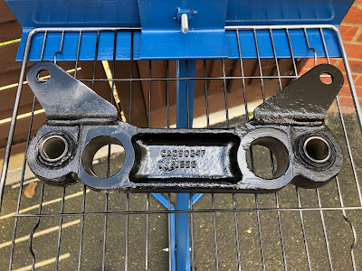
Followers of this blog will recall that I had to obtain a second wishbone tie as the original one was missing a couple of the bushes and that these particular bushes are not available as a replacement part.  I spent a lot of time cleaning up the original wishbone tie, as well as the replacement, and now the reason for that effort can be revealed!!

Since the bushes can not be replaced, I was worried about damaging them while pressing them out to enable the wishbone tie to be powder coated.  I was also concerned that trying to powder coat the wishbone tie with the bushes in-situ would result in the bushes melting during the curing process!  Jon at AK had assured me that I could powder coat with the bushes in place, but I was still a bit nervous and decided to do a trial run on the original tie.

I followed the same process as for the hubs, pre-heat to "degas", degrease and clean, coat and cure.  The test was pretty successful although as a result I did make a few adjustments to the process.


Wishbone Tie - test

The wishbone tie is a pretty substantial lump of metal and during curing took around 50 minutes for the surface to get up to temperature.  Although the bushes didn't melt as I had feared, during the pre-bake and curing there was a pretty distinct smell of hot rubber; as result, for the actual tie, I lowered the temperature for the pre-bake to 200 degrees C and used Satin Black powder from ElectrostaticMagic which only requires 10 minute curing time at the lower temperature of 180 degrees C.  


Wishbone Tie - Final Result

Wishbone Tie - close-up of finish

Next up was the rear pendulum bracket - another substantial chunk of metal casting!  Although I have obtained new bushes for this part, I coated it with the satin black powder to match the wishbone tie.  In fact I did all the parts for the rear diff in satin black.  The process for all these parts was as previously described.


More sweeping of the drive required...


Pendulum after blasting and cleaning

Powder coated and reading for curing

Fresh out of the oven..

After cooling and removal of masking tape

Close-up of finish

Next up was the rear diff mounting bracket and the compliance buffers (which for the PowerLok differential are solid metal spacers as opposed to the rubber ones for the normal differential units).  The donor rear bracket was quite corroded and very pitted in places.  It needed some considerable work with the sand blaster, the angle grinder / flappy wheel combo and a dremel to get it cleaned up.  I still couldn't quite remove all the pitting though and final finish was not as great as I would have hoped.


Rear Bracket after some initial grinder / flappy wheel action...

Pitting needed a lot of grinding to remove...

After blasting and some treatment with the angry end of the Dremel
Coated parts for rear diff mounting

Some pitting still visible on final coated bracket

So with all those parts coated I am now in a position to finish off the front hubs and start mounting the rear differential.  Just need a wet weekend now then....


Powder Coating Fest - Part 2

In between getting on with the assembly of the front and rear axles, I have been continuing to clean and powder coat many of the donor parts in readiness for reassembly.

The budget sandblaster has been busy - now powered by my new 3hp /100-litre air compressor, which was a present to myself for a recent major milestone birthday.


Bigger is better!

I also have also tried out some different blasting media.  

I was quite happy with the results using the Wickes Kiln Dried Sand; well at least with the first bag I had bought.  When I bought the second bag, the sand was more like builders sand, quite soft and slightly damp, and just clogged in the nozzle of the blaster.

So I splashed out on 25kg of Fine Glass Grit from Amazon and 25kg of Fine Aluminium Oxide from Frost.

I have had some great results with the aluminium oxide.  It strips paint, rust and clag off in next to no time.  It's far more brutal than the sand, both on the metal parts and on exposed skin!  


Aluminium Oxide blasting media

The glass grit is a more gentle blasting media and is good for removing light rust and cleaning up the machined surfaces of some of the donor parts.


Fine Glass Grit blasting media

HEALTH AND SAFETY TIP - As with the sand it is important to wear eye protection but I found it necessary to upgrade to a full set of enclosed safety goggles (after learning the hard way that aluminium oxide grit is very sharp and will find its way into your eyes while just wearing an ordinary pair of safety glasses).  Also with both the aluminium oxide and glass grit, I would recommend a good quality dust mask; both media have a lot of very fine particles which I have no doubt are not good for the respiratory passages.

The pictures below show one of the rear stub axles before and after blasting.  The aluminium oxide cleaned off all the old paint in less than 10 minutes (the kiln dried sand would have taken over an hour) and then I used the glass grit to clean up the splined shaft and threaded end of the shaft.


Prior to a good gunking!

Post gunk...(zip ties used to identify parts from offside driveshaft)
After 20 mins of the budget blaster with Aluminium Oxide / Glass Grit media

After my problems with the front hubs and the development of further rust/corrosion between blasting and powder coating, I decided to try out Eastwood's After Blast Metal Prep.  


A gallon of SlartyAfterBlast...

This stuff is supposed to clean and degrease freshly blasted metal and also contains phosphoric acid to etch the metal surface and leave a zinc phosphate coating to prevent flash rusting and give a good surface to aid adhesion of paint or powder coat.  It's not cheap, at £45 a gallon from Frost, but if it does the job and saves me sandblasting everything twice, then I guess it will be worth it.

I bought a cheap spray bottle and used it to spray the parts with the After Blast.  The instructions say to leave it for 2-5mins and then to wipe off with a clean cloth to remove any excess contaminants and excess spray.


The inboard Drive Shaft Saddle after After Blast treatment...

A couple of tips for using this stuff:

1) Do make sure any excess liquid is wiped off - if it's allowed to sit on the part it  develops into large blobs of zinc phosphate coating

2) Avoid machined surfaces - since the spray etches the surface of the metal you want to avoid getting any spray on these surfaces and it will change the surface texture (i.e it's no longer smooth and machined!)

I made these mistakes the first time round on one of the inboard driveshaft saddles and ended up having to clean up the areas with a brass wire wheel in the angry end of the drill.

But the stuff does seem to work - I blasted the inboard driveshaft saddle a couple of weeks ago and no further rusting / corrosion had developed by the time I got round to powder coating.

Below are a few pictures of various parts in preparation and after powder coating.  


Rear Hub and Stub Axle prior to blasting


The backside of the Rear Hub after blasting...

...And the front face
Hub getting an After Blast bath (avoiding the machined surfaces)
Inboard Driveshaft Saddle fresh out of the oven
Freshly coated Hub and Drive Shaft ends

Differential - Part 2 - Being Granted Two Wish(bones)....

With the differential unit in place, next on the list was to install the rear wishbone tie. A simple task from looking at the AK Build Manual.  Well...not quite!

First up was to install the donor mounting bracket, which is simply slid over the main rear differential bolts.


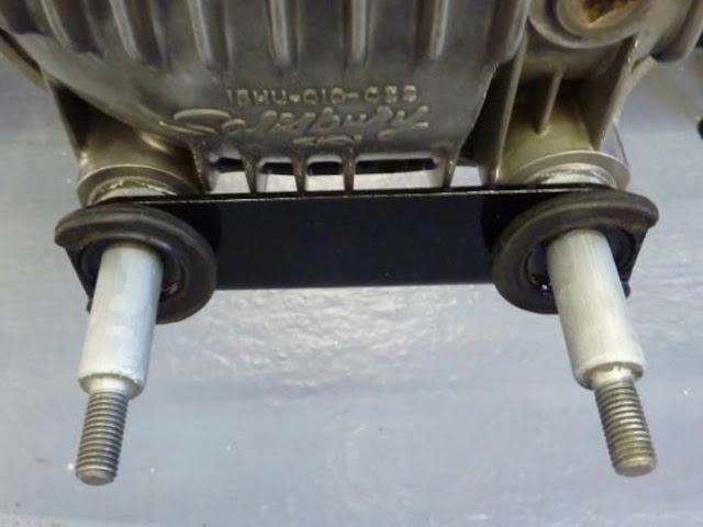
Wishbone tie (top), Mounting Bracket (middle) and Compliance Buffers (bottom)


Mounting bracket installed...

I then applied copper grease liberally to the main rear diff bolts and installed the inner compliance buffers (the ones with the big hole which fits over the main bolts); these are installed with the flat edge towards the outside of the chassis.


Inboard Compliance Buffers installed...

All nice and straightforward so far!

Next on was the wishbone tie; this is installed with the side marked "Jaguar" facing towards the rear of the chassis.

Wishbone tie in place - I see a problem looming...

The outer compliance buffers are then installed again with the flat edge facing outwards.

Hang on!  There's no thread of main rear diff bolts protruding out of the assembly to get the M12 Nylocs onto! WTF!!

Bugger...!

After much head-scratching, drinking of tea, internet research, taking it all apart and reassembling (hoping for a different result), and a teeny bit of swearing, I was none the wiser and I still had no protruding thread onto which to attach a nut...

The problem it seemed was simple; the flange on the back of my compliance buffers seemed to be too thick/big to allow the buffer to sit tightly against the wishbone tie.

This doesn't look right...

Then I remembered something fellow builder Richard had said to me when he was round and I had shown him some of my first attempts at powder coating; which happened to me a couple of the metal compliance buffers.  Richard had said that his buffers/spacers were completely different; they were rubber with a metal insert.

So I had a closer look at the AK Build Manual and the buffers/spacers in the photo in the manual looked completely different from mine.

These are not my spacers! - Photo courtesy of AK Sportscars Ltd

Then I had a lightning bolt moment and I dug out the original wishbone tie that I had received from Simply Performance with my donor axles; remember the one that I had assumed was missing the inner bushes.

Well, guess what - the flange on the back of my metal buffers/spacers seated exactly into the recess in the wishbone tie where the inner bushes should have been fitted.

Fits like a glass slipper!

A quick email to Jon at AK and he confirmed that some of the Jag rear ends did come with a solidly mounted wishbone tie.  So it was a good job I kept the original wishbone tie and even better, I had decided to powder coat it as well! (Although the finish was not as good as the tie that I thought I was using - so I might need to consider recoating it at some point).

Armed with that knowledge, I tried reassembly with the original wishbone tie, and this time it all went together beautifully and I ended up with a goodly amount of thread from the main rear diff bolts sticking out to get the M12 Nylocs and washers onto.

Looking more promising...

Result!

So after several hours attempting a job that should literally have taken five minutes, I need a lie down...or a beer...or both!

Saturday 6 July 2019

Differential - Part 1 - Differential Equations

Having done as much as I can do for the time being on the front end build, it was time to start on the rear end build.

The first task was to press some new bushes into the newly powder-coated pendulum bracket.  The replacement bushes were ordered from SNG Barratt as follows:


More bits courtesy of SNG Barratt

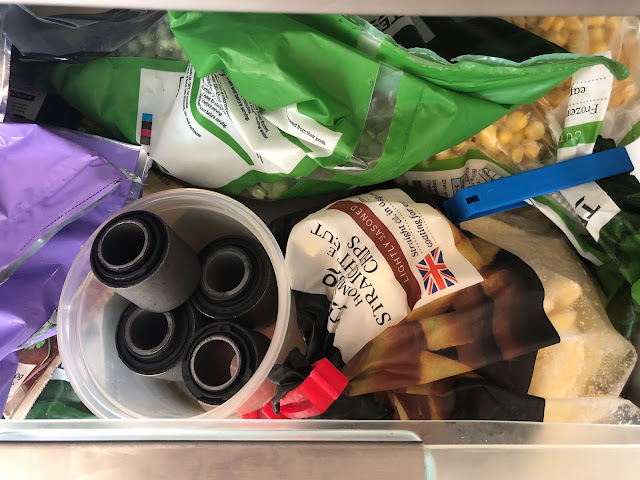
To (hopefully) make the installation a little easier I left the pendulum bracket out in the sun for an hour or two to warm up nicely and put the new bushes in the freezer for a few hours.


Bushes and chips for tea?

I lightly greased the bush housings in the pendulum with copper grease and then pressed the new (cold) bushes into place using my 12T press and a suitably sized impact socket as a drift.  Note that one side of the bush housings on the pendulum has a bevelled edge which helps hold the new bush in position and guides it into the housing when starting to press it in.


Greased bore - note bevelled edge to ease bush insertion...
Pressing bushes into place
All bushes replaced

Next, it was time to unbox the rear differential unit.  The diff is a Salisbury Power Lock (limited-slip) unit with a 3.58 final ratio.  This was fully refurbished by Simply Performance when I purchased the donor axles and has sat in a large box occupying a large space on my garage floor ever since.  The unit is also bloody heavy and I needed some help from Sam to lift it out of the box and onto the cup of my 3T trolley jack.


Shiny refurbished differential unit

The pendulum bracket is then fitted over the nose of the differential with the side marked "Jaguar" facing towards the front of the car.  The upper bushes of the bracket slide onto the shafts at the front of the diff; these had a generous application of copper grease prior to installation.


Pendulum Bracket in place

The rear upper differential bolts are M12 by 70 bolts which are supplied by AK, with M12 washers to sit under the bolt head and 35mm by 14mm washers which are used as spacers between the diff and the chassis.  I assume the 35mm diameter washers are supposed to fit into the recesses on the top of the diff unit but mine did not seem to sit properly and allow the M12 to pass through so I ended up having to flat off the bottom of the washers on the bench grinder.


Rear Diff Bolts and Spacer Washers - Photo courtesy of AK Sportscars Build Manual
"Modified" Spacer Washers

With some careful (skilful?) control of the jack, I managed to raise the differential unit up and slide it forward into position relatively easily (just remember to rotate the input yoke on the diff so that it passes through the aperture in the chassis first).

Then it was just a case of securing all the fasteners (M10x1.25 nuts on the diff nose studs, M16 Nylocs with 1.25" by 5/8" washers on the front diff studs and M12 Nylocs and M12 washers on the rear diff bolts) to hold the diff in place and allow removal of the jack.


Differential installed!

I haven't fully torqued up any of the fasteners at this stage, mainly as I haven't worked out which are the correct settings from the Jaguar XJ40 Haynes Manual yet.  However, from reading Richard's blog and the trouble he had getting the differential tie bar into place, I figured leaving the diff fasteners not fully tightened might allow some play to get the diff tie bars fitted.

Watch this space!