Showing posts with label Rear Axle. Show all posts

Wednesday 28 September 2022

Brakes - Part 3 - Rear

 The rear calipers supplied AK Big Brake upgrade kit usually are designed to work with 295mm diameter by 10mm thick rear discs (non-vented).  As my donor car came with 305mm diameter by 20mm thick vented discs I was keen to retain this setup.  Fortunately, HiSpec (who make the upgrade kits for AK) were able to adapt the spacer between the two halves of the caliper to accommodate my larger and thicker discs.

As at the front, the new rear calipers are larger than the original donor single-pot items but weigh in at 1.7kg compared to the 2.06kg of the originals.  They also benefit from two pistons per side to improve the application of braking pressure to the pads.

Size comparison - original caliper looks very sad in comparison

2 pistons per side compared to the single piston original

New Ferodo pads (left) are similar in size to the originals

I ordered some new rear discs from EBC brakes.  I went with their USR Sports Series disks which are slotted and come in a black thermic coating to help combat corrosion.

As with the front calipers, the kit comes with new brackets and bolts to fix onto the rear hubs onto which the callipers are attached.  I fitted these and torqued the mounting bolts to 60Nm/44lbf-ft.  

New caliper mounting blocks and bolts - with confirmation that they have been adapted for 305 x 20mm discs

I inserted the brake pads before installing the calipers - again this could be done with the caliper on the car but I figured it would be easier to do it on the bench (or floor as it turned out).  For the rear pads, the kit comes with some springs which need to be slid onto the outer edge of the pads.  I remembered to give the back of the pads a smear of copper grease before inserting them into place.  They are secured by two pins held in place with R-clips, the springs on the pads need to be eased under the pins as they are inserted to hold the pads into place.

Brake pad spring installed on the outer edge of pad...

...and a smear of copper grease added to the rear of pad...

...before pads inserted into caliper and held in place with retaining pins.

The last task before the final installation of the calipers was to adjust the handbrake adjusters on both sides so that the handbrake pads were just rubbing on the inside of the discs (although I think some further adjustment may be required at a later date). I could then bolt the calipers to the mounting blocks and torque the bolts up to 60Nm/44lbf-ft.  

Rear brake discs and calipers done!

And with that, I have probably reached the stage of the build that I was originally hoping to get to at the end of 2019...so only 3 years behind schedule!

Tuesday 27 September 2022

Rear Axle Reassembly - Part 11 - Finally completed

Once my new half shaft spacers had arrived I could get on and (hopefully) complete the rear axle assembly.

Upon removing the spacers from the packaging, I was disappointed to find that they were both made from steel, and not some more exotic metal, as the price I paid for them might have suggested.

Could a golden spacer lie within...No!

I installed both spacers (4mm on offside / 7mm on nearside) and a single rear camber shim on each side initially.  It actually turned out that I needed just the single 4mm spacer on the offside and the 7mm spacer plus two shims on the nearside to get a camber setting of 0.3 degrees negative on both sides.

Spacer in place on differential output flange

Oh look - those shims do fit after all...


0.3 degrees negative on that side...

...and 0.3 degrees negative on the other side.  Job done!

With that done, I could remove all the 7/16" nuts from the half shafts for the last time and replace them with 7/16" Nylocs.  These were torqued up to 90Nm / 66lbf ft.

The next job was to remove the original drive nuts from the hub end of the half shafts and replace them with new items.  The Jaguar service manual recommends that the splined end of the half shaft within the rear hub is covered in thread lock over 30-50% of the radial area.  I used Loctite 270 and covered the rear part of the splined section before reassembly.  As well as a new drive nut I also replaced the conical washer with a new item.  

Today's thread lock is Loctite 270...

...applied over the rear of the splined section

New conical washer and drive nut (note the red insert)

The drive nuts need to be tightened up to a whopping 225lbf ft / 305Nm of torque.  I tightened them up initially using my air spanner.  I then used a large pry bar against the wheel studs and braced against the floor to stop the hub from rotating and dug out the largest of the torque wrenches from my tool arsenal.

Top tip - push the wrench down rather than trying to pull it up or side on otherwise you may end up pulling the chassis off the axle stands.  Also, try and position yourself away from the pry bar.  Mine ended up bending like a banana and if it were to break free from the wheel studs, it will cause serious damage!

Drive nut installed and tightened to ridiculous torque level!

The last step was to install the rear shock absorbers.  These are fitted in place with 7/16" x 4.5" bolts, M12 washers and 7/16" Nylocs in the top mounts and 7/16" x 2.5" bolts, M12 washers and 7/16" Nylocs in the bottom mounts.  AK only appear to supply a single M12 washer per bolt so I splashed out and added an extra washer to have one under the bolt head and one under the nut on all mounts.

Shiney new shock absorber - fitted so adjuster knob is at the bottom and facing inboard.

Mounting bolts - these were given a liberal smear of copper grease before installation

Rear Shock Absorber installed

The final step was to torque down the shock absorber mounting bolts to 38Nm (28 lbf ft) for the upper mounts and 64Nm (47lbf ft) for the lower mounts.  And that is the rear axle finally completed!

Sunday 25 September 2022

Rear Axle Reassembly - Part 10 - Shafts and Shims Shocker

 Finally, I am at the last stage of getting the rear axle/suspension back together and be warned this stage is a right PITA.

The first job on the list was to set the rear camber.  This requires setting the top most point of each of the rear hubs to be 150mm below the top of the rear chassis rail, checking the vertical angle of the face of the rear hubs and adjusting (by inserting shims between the differential output flange and the inboard half shaft flange) until the camber of the rear hub is between 0 and 0.5 degrees negative camber.

There now follows a moment of monumental stupidity which I am amazed I am prepared to admit to on such a globally viewed forum.

There are a couple of options for shimming out the half shafts on a Jaguar rear axle.

  • Spacers of a specific thickness.  Jaguar used spacers of between 3.5 and 7.5mm thickness with Part Number CBC4806xx, where xx is the spacer thickness (e.g. 35 for the 3.5mm spacer).  Although these are only made out of steel, at the price they cost, you would think they were made out of gold!
  • Rear camber shims with Part Number C16621#.  These are 0.020" (approx 0.5mm) thick and cost less than £1 each

I went with the second and cheaper option and ordered 16 shims from SNG Barratt hoping that would be a sufficient number (giving me up to 4mm of shim on each side).

16 Rear Camber Shims for less than £20...

I jacked up the first rear hub until it was 150mm below the top of the chassis rail.  I did this by clamping a spirit level to the top of the chassis rail and setting an adjustable set square on top, with the ruler set to give a depth of 150mm below the bottom of the spirit level.  The hub was then jacked up until it just touched the bottom of the ruler.

Setting height of hub to correct level

I then checked the vertical angle of the hub using a digital spirit level set vertically across the edges of the centre spigot on the hub.  The first reading was 89.25 degrees (i.e 0.75 degrees of negative camber), slightly too high, so some shimming was required.

I found an article on one of the online Jaguar forums that suggested that each 0.5mm shim would adjust the camber angle by around 0.25 degrees. So theoretically I only needed to add one shim.  In reality, I needed to add a few more as, without any shims in place, there is a small flange on the back of the inboard half shaft that bears onto the differential output shaft flange, such that at the point where the bolts pass through there is a gap between the two of around 3.5 to 4mm.  Until that gap is filled, the rear camber shims won't actually have any effect at all.

So I undid the nuts on the inboard half-shaft, which is a bit of a pain as you have to get it in exactly the right spot to get a 7/16" socket in through the U-joints and then you have to turn the differential by hand to line up each nut for removal (and of course repeat the process when you put the nuts back on).

With the half-shaft eased away from the differential flange bolts I could slide on a couple of shims, tighten it all back up and recheck the camber.  Except I couldn't because the hole pattern in my shims did not match the bolt pattern on my differential output flange; two of the holes matched up, but two were way out.

Cue much swearing...

In order not to waste the whole afternoon, I rummaged around in my box of leftover donor parts and found the two original (thick) half shaft spacers.  So I decided to install those just to try and get an idea of what thickness of shimming I was going to need.  After a frustrating and knuckle scraping afternoon of removing and reinstalling the half-shafts on both sides (several times), I had concluded that I was going to need around 4-4.5mm of shims on the offside and 7-7.5mm of shims on the nearside.

Later that afternoon I logged onto the SNG Barratt website to check out spacer options again.  This time I entered the VIN number for my donor vehicle and surprisingly the rear camber shims that I had already bought, did not come up as an option.  The only options were for the fixed-thickness spacers made of gold.  Clearly, I thought, the rear camber shims are for a different year model which has a different bolt pattern.

Annoyingly the spacers were also all on Special Order from SNG.  However, I found them in stock at Jaguar and Landrover Classic Parts.  I decided to order a 4mm and a 7mm spacer and then if necessary I could cut up the rear camber shims in such a way as to make one spacer out of two (or more) if additional thickness was needed.  BTW these two spacers cost over £100...

While I was waiting for the new spacers to arrive, I decided one evening to try and work out the best way to section up my original shims to try and make up a single shim from bits of others.  

It was then that my moment of stupidity hit me right between the eyes...

Why would they change the bolt pattern...

...Oh wait - they didn't...Doh!


Still...on the plus side, with needing nearly 12mm in total of shimming, I didn't have enough rear camber shims in any case plus its probably better to have a solid spacer rather than a large number of the thinner shims, particularly on the side needing nearly 8mm of shim (which would be 16 of the rear camber shims).

So maybe it has all worked out for the best!


Thursday 18 August 2022

Brakes - Part 1 - Decision Time

My original intentions for the brakes on Project Snake were always to refurbish and reuse the original brakes from the donor car.  As Jon at AK told me "if they are good enough to stop a 2.5tonne Jag, they're good enough for a 1.4tonne Cobra".

When I sourced the donor parts from Simply Performance, they suggested that getting the biggest brakes possible from the outset would be the best path to take.  I wanted vented discs on both the front and the rear and Ben at Simply Performance suggested using a car with the larger XJ twin-pot calipers at the front.  Seemed like a good suggestion at the time and that is what I went with.

So the brake discs and calipers I got with the donor vehicle are summarised below.

The eagle-eyed amongst you will spot that the rear disc diameter is larger than the front, which is unusual.  Usually, under heavy braking and weight transfer towards the front end of the car, it is the front brakes that do more work in bringing the car to a halt, and hence traditionally they are larger.  I assume that the use of the twin-pot caliper at the front provides enhanced braking performance over the larger disc / single-pot caliper arrangement at the rear and allows a slightly smaller disc to be used. But who knows what was in the mind of those engineers at Jaguar?

It seems however that those twin-pot front calipers are a bit of an enigma.  Whichever of the usual Jaguar part suppliers I looked at to try and find service parts for these calipers, they didn't seem to exist.  Even typing my donor car VIN number into various parts websites still kept on bringing up the single-pot caliper.

Twin-pot Front Caliper

Single Pot Rear Caliper

Disc Thickness (Thicker Front on Left)

Disc Diameter (Smaller Front on Left)

Front disc 10mm smaller diameter than Rear...?!

I contacted Ben at Simply Performance and he suggested that maybe if I measured the piston diameter in the caliper then I might be able to find suitable replacement piston/seal kits from another caliper option.  No joy there; the diameter of the twin-pot pistons is smaller than any of the other standard front (or rear) pistons in the various calipers over the years.

I did find a couple of places online that claimed to be able to refurbish the calipers, but given my failure to find any semblance of service parts for these unicorn calipers, I wasn't convinced.  I did eventually discover that Ward Engineering in Colchester, which is a specialist in the supply of reconditioned Jaguar axles and brakes, did offer a reconditioning service for the twin-pot calipers.  However, by then, my plans had taken a slight change.

Switching from an LS3 engine to an LS7 with close to 660hp got me thinking that, despite Jon's adage above, rapid and stable deceleration was going to be a top priority.  The oddity of the smaller diameter front discs compared to the rear on my donor vehicle was also starting to perturb me; I didn't want any unexpected twitchiness under heavy braking.

So when the UK taxman gave me a very unexpected but very well received tax rebate, my mind was made up.  It was time to buy an AK Big Brake Upgrade Kit!

Sunday 7 August 2022

Differential - Part 5 - We need to torque!

 There were a couple of small jobs that I needed to do to complete the installation of the rear differential.

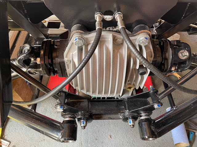
The first was to cut down the 7/16UNF bolts securing the tie bars to the differential and the chassis.  The threaded length of these bolts is much greater than actually required and the protruding length looks a bit odd (to me anyway).

The second was to actually torque up all the various differential mounting bolts.  I didn't do this at the time of the original installation as, quite simply, I couldn't find the details for the necessary torque settings.

An offensive amount of bolt sticky-outedness...

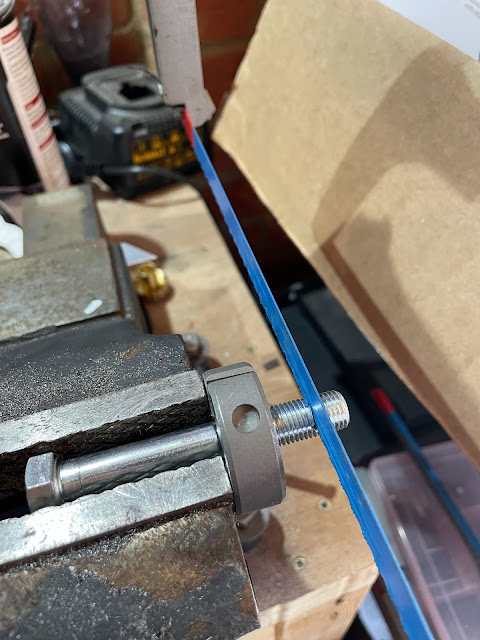
I reckoned about 10mm off the end of the tie bar bolts should suffice.  Before cutting I wound a 7/16UNF die onto the bolt a) so that I could make sure the threads were intact after cutting and b) it made a handy brace to help support the bolts in the vice while cutting!

Die used to help keep bolt in place while cutting

I cut down the bolts with a hacksaw and then reinstalled them into the tie bar mounts, with a further liberal application of copper grease, adding a 7/16 washer on each end and 7/16UNF Nyloc nuts.  The final result was far more pleasing to my eye!

Much better - no unnecessary protrusion!

Now to finish tighten up all the differential mounting bolts.  You would have thought it would have been a relatively simple task to find all the necessary torque specifications, but oddly enough it took me a fair bit of searching before I was sure I had the right values.  This is complicated slightly by the fact that the AK mounting arrangement for the differential is of course not quite the same as the original Jaguar arrangement but my research was also hampered by the various Jaguar service manuals not calling any of the parts/bolt descriptions by anything remotely helpful!

I finally stumbled across a version of the Jaguar XJ40 Workshop Manual on the Jaguar UK forum.  This has a very handy series of diagrams at the front which show the various assemblies throughout the car and the necessary torque settings.  I almost missed this as I initially scrolled straight to the Final Drive Chapter (where of course everything was not called what I expected it to be).  Fortunately, I spotted this section as I was trying to refind the index!

The necessary specifications are as follows:


I was then able to finally tighten all the differential mounting bolts to the required specification and mark them as tightened with my favourite shade of blue nail varnish.

All torqued up and ready to go!


Saturday 6 August 2022

Handbrake Part 1 - Blue Suede Shoes

Once the backing plates were reinstalled back onto the rear hub carriers, but before the carriers go back onto the car, it's time to get the handbrake shoes and associated bits fixed in place (I also figured it would be easier to carry out this operation before the hubs themselves are reinstalled).

It goes without saying that for the rebuild I purchased a new set of handbrake shoes for both sides of the car; also if you recall the old shoes had disintegrated to dust when I disassembled the rear axle originally.

I was going to re-use the adjusters and the handbrake levers from the donor car.  But after several attempts to try and clean them up, the residual caked-on brake dust seemed reluctant to give up its grip on these parts so I gave in and ordered new parts and new brake shoe springs at the same time.

The handbrake shoes are fixed to the backing plate with a spring-loaded pin; these have a T-shaped end that passes through the backing plate and is locked in place by turning through 90 degrees.  Those following the story closely will recall that the T-slots on my donor backing plates (even the replacements from Simply Performance) were shot and I wasn't convinced that there was enough metal left to provide a robust anchorage point for the brake shoe fixing.

That well-known auction site came to my rescue again and I managed to buy a set of replacement pins - these were basically a long M4 bolt with a Nyloc nut.  Using three M4 washers per bolt, one on either side of the compression spring and then one between the M4 Nyloc and the backing plate (to further assist in the prevention of the bolt pulling through the backing plate) a suitable replacement fixing was achieved.

My total shopping list for the handbrake rebuild was as per the Table below.  I have to admit the cost of the replacement adjusters and levers was slightly eye-watering but at least being brand new parts I can be assured that these will (hopefully) move freely and work as planned.


Advance warning - installing the handbrake shoes is a pig of a job.  There seem to be many ways to do it, including the method outlined in the Haynes manual, which frankly, due to the tension in the lower spring, strikes me as impossible!  I did wonder whether it would be easier to have actually done this with the hub back on the car, with the rest of the chassis acting as additional ballast to help when trying to stretch the springs; however, for me, I think it was easier (?!) doing this operation on the workbench rather than trying to do it sat on the floor.

So this is how I did it (other methods are available).

New parts for handbrake rebuild

There are six small raised pads on the brake backing plate that the handbrake shoes rest on and the first step was to put a small amount of copper grease onto each of these.  You need to take care not to put too much grease on (as with all the following steps) as brake linings and grease do not mix.

Location of raised pads on back plate

I then disassembled the new adjusters and gave the screw threads and recess a generous smear of copper grease.  The brake shoes also got a strategic greasing, where the upper and lower tension springs hook into the shoes and also where the adjuster and actuating lever locate onto the shoes.  Finally, I put a smear of copper grease on each side of the mounting block on each of the back plates.

With the brake shoes on the bench, I wound down the adjusters to their shortest length, placed them between the tops of each pair of brake shoes, and then inserted the upper and lower tension springs into their respective holes.

I then placed the brake shoe assembly over the hub carrier and onto the backing plate.  At this point due to the tension in the lower spring, the bottom of the brake shoes will be too close together to fit either side of the mounting block on the back plate.

There then ensued a short wrestling match as I tried to keep the brake shoes flat against the back plate (to stop the tension springs pinging out of their locating holes) while at the same time trying to pull the bottom of the shoes apart sufficiently to get them to sit either side of the mounting block.  Oh and while all this is going on, I was trying to avoid getting all that grease that I had strategically applied to all the contact points ending up getting smeared all over the brake friction material. 

And the winner, with two falls and a submission...

I was pleasantly surprised that once the shoes were in place, the installation of the replacement spring-loaded pins was very straightforward; I anticipated further wrestling to get the holes to all lineup, but everything seemed to line up straight away.

I was initially a bit perturbed that the upper tension spring doesn't sit straight and clashes with the adjuster.  However the adjuster still seemed to move and the proximity of the spring does have the added advantage that it helps to prevent any rotation of the adjuster cog under vibration, so it's staying as it is!

The actuating levers then received a generous greasing of all the moving/contact surfaces.  The new AK handbrake cables were then passed through from the rear of the hubs and fixed into the new levers with the studs from the original levers.  Thankfully I had not thrown these away, the new levers do not come with a new stud and the part is not available for purchase. 

Lubricated lever and the donor stud for securing cable

The levers can then be installed between the lower ends of the brake shoes.  This needed a bit more wrestling and the gentle application of a small pry bar just to ease the shoes apart sufficiently to allow the lever to drop into place.

Completed handbrake rebuild

Job done - and frankly not one that I would be in a rush to want to have to repeat!  Now I can finish off the rear hub installation onto the chassis.


Friday 5 August 2022

Rear Axle Reassembly - Part 9 - Hubs On....Finally!

Finally, the day has come when, having messed around for so long, I am hoping to get the rear hubs onto the car at last.  I had already purchased some of the new parts required for this momentous day from SNG Barratt many moons ago, as per the table below:


The first operation of the day was to secure the brake shoe mounting blocks to the backing plates using some M6x10 screws with spring washers.  I added a dobble of Loctite to these for good measure.

Brake shoe mounting block...mounted!

My new spacer tubes were inserted to place, the backing plate placed over the hub, and secured using new fixings all around.  Each plate needs two M10 screws and two M6 screws; the M10s come with thread lock compound already applied to the threads, I added some extra to the M6 screws.  These were tightened evenly using TPS45 and TPS25 bits until the backing plate was snug against the hub carrier.

Lower M10 Mounting Bolts with factory applied thread lock

I then spent some considerable time grappling with the installation of the handbrake shoes and springs (Handbrake Part 1) before it was time to reinstall the hubs.

These were given a liberal application of grease before being pushed firmly into place.  The hubs were then turned over and the ABS ring tapped onto the back of the hub using a large piece of timber as a suitable drift and a large hammer to provide the force!

Hub greased prior to insertion...

...ABS ring tapped firmly back into place...

...and one completed hub ready to go onto the car!

Finally, it was time to get the hubs on the car!

First step - install the hubs onto the lower wishbones.  This required the use of two new spacers per hub, which were installed on the face of each of the fulcrum bearings with a good smear of copper grease to hold them in place during installation.  I just ordered four new 3.955mm spacers (the same size as my donor spacers) since (according to the AK gospel of Jon Freeman) the shimming / preload of the lower fulcrum bearings is not important so long as the wishbone bracket is pulled tight against the hub.  As it was, the new spacers were just about the right thickness, and just needed a gentle tap with a soft mallet to ease the lower part of the hub into the wishbone bracket.  I gave all the contact surfaces a light smear of copper grease prior to installation.

The lower fulcrum bolt was given a very liberal application of copper grease, tapped gently through the lower wishbone mount, and secured with an M14 Nyloc and washer - just snugged into place for the moment.

The driveshafts were then installed onto the differential and held in place with plain 7/16 inch nuts.  I installed the driveshafts without any shims/spacers between then and the differential flange; the camber will be checked and the required shim thickness worked out next.

The drive shafts were then installed into the hub, which required a bit of manipulation to get the relative angles correct to allow the shaft to slide into the hub, before securing with the original cone washer and drive shaft nut.  The cone washer, drive nut, and differential flange nuts will all be replaced with new items once the camber has been set and final shims installed.

Hub and spacers tapped into lower wishbone mount

The last time I can say it - a heavily greased shaft!

Differential flange set up with no spacers/shims

Hub installed - it feels like a major milestone!

The final finishing touch was to make some plates to cover the hole for the ABS sensor in the top of the hub carriers.  Most people seem to leave these open but that just offends my sense of perfection!  

I made up a greasy finger paper template, stuck this to a piece of 2mm sheet steel, and cut/filed this down to the required profile.  The fixing hole locations were marked out and drilled with a 6mm drill.  The plates were of course treated to some candy red powder coating (as with all the other bits that won't be seen on the final car...).  I also cut out a couple of gaskets from rubber sheet, to match the outline of the plates, and then these were fixed in place with some stainless steel M6 button head screws with spring washers.

Greasy finger paper template

Powder-coated plates and rubber gaskets

Cover plate fixed in place

A very productive day - time for a well-earned beer me thinks!