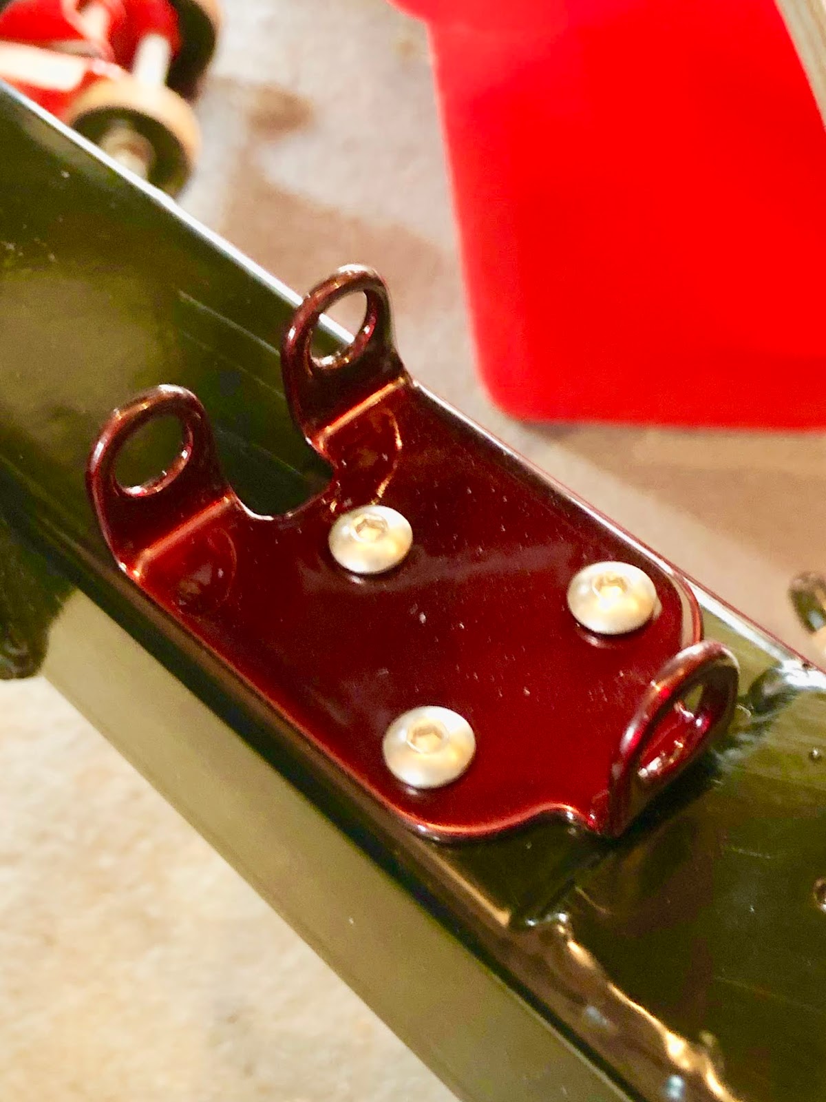
With the brake/clutch pipe routing finalised and the bulkhead bracket in place, it was time to master the art of bending and flaring brake lines.
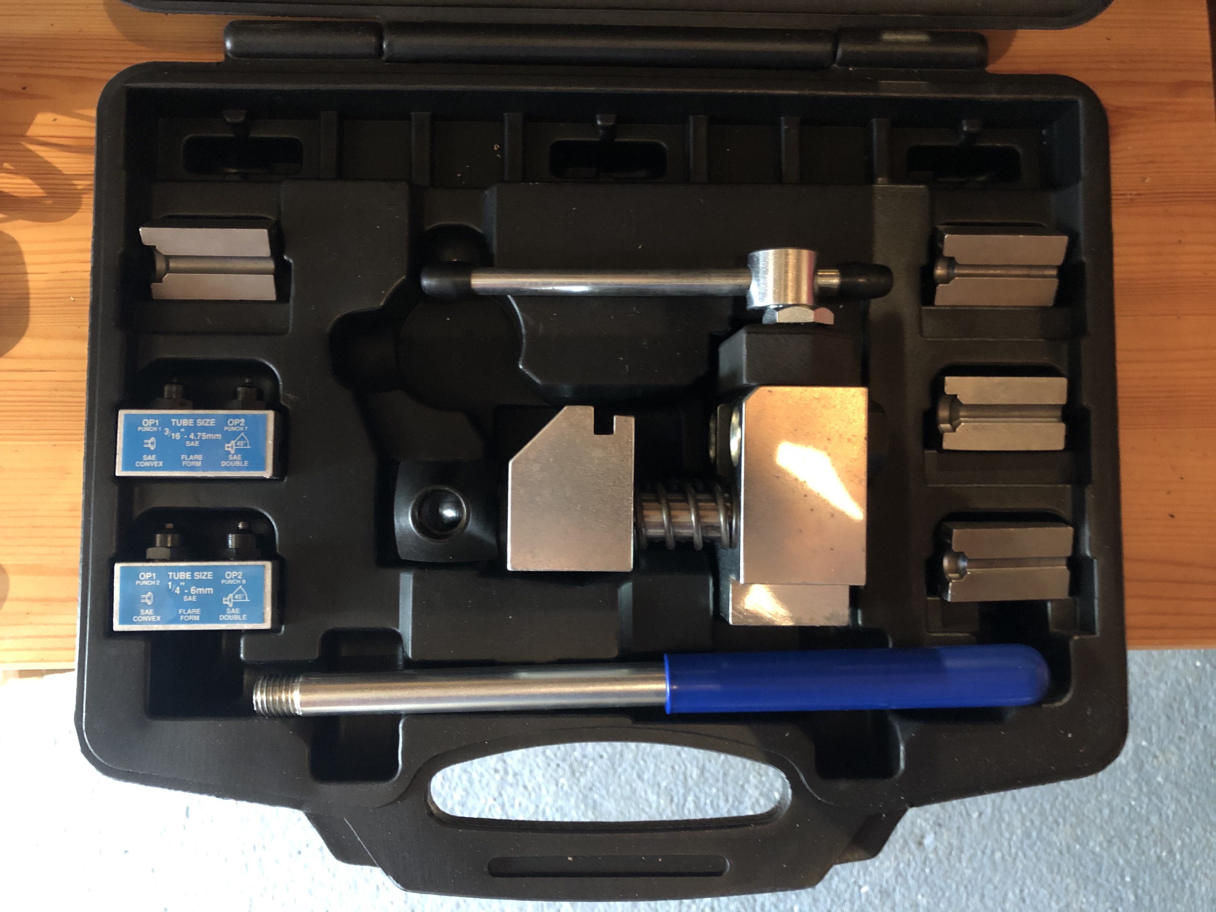
To form the brake line flares I have invested in a heavy-duty flaring tool from Car Builder Solutions. This is a vice mounted tool with the advantage that it came with the dies and punches to form male and female flares in both 3/16" and 1/4" pipe.
 |
Brake Flaring Kit from Car Builder Solutions
|
I also bought a Brake Pipe Bender from Frost Restoration. There are many similar tools available but I liked the look of this one as it seems to fully support the pipe around the whole bend during the forming operation, avoiding any risk of kinking or crushing the pipe. Again it also has the advantage of being suitable for 3/16" and 1/4" pipe. More on this later...
 |
Pipe Bending Tool
|
I also purchased a 25ft roll of 3/16" copper-nickel brake pipe from Car Builder Solutions and a slightly more expensive 25ft roll of 1/4" copper-nickel pipe from Frost for the clutch line (unfortunately Car Builder Solutions don't sell 1/4" line) and the following brake fittings from Automec.
I did a few test flares on a few short lengths of pipe to check the flaring operation. I used a simple pipe cutter to cut the pipe to length. I did actually buy one from Car Builder Solutions when I ordered some other bits but a plumbers pipe cutter from any DIY store will do the job.
 |
Standard Pipe Cutter
|
The cutter does leave a bit of a burr on the cut end of the pipe. Again I did invest in a deburring tool from Car Builder Solutions but I have to admit to not being impressed - it does a nice job of chamfering the outside of the pipe but makes a bit of a ragged job of the inside which I ended up cleaning up with a countersink bit in a hand drill. I reckon that better results could be achieved with a fine file and a countersink bit alone.
 |
Pipe Deburring Tool - deburrs inside and outside of pipe in one operation
|
 |
| Pipe after cutting - raised burr visible |
 |
| After Deburring tool - outside edge looks OK but inside looking a little ragged |
 |
After using countersink on the inner edge
|
With the pipe cut and prepped it is ready to be flared. The end to be flared in placed on one side of the appropriate die block, the other half is placed on top and the pipe adjusted so that the end of the pipe is flush with the end of the die; I left the pipe protruding a bit and then used a steel rule to push it flush with the end of the die. The die block and pipe are then clamped into the flaring machine (note that this does not have to be tightened up with any significant force - I have read reviews where people have split the die block by overtightening - hand tight and a bit seems more than sufficient).
 |
Two halves of the 3/16" die block
|
The flaring operation is then either a one or two-step process depending on whether a male or female flare is required. The first operation is always to form a male flare using the appropriate size OP1 punch on the flare tool. I found it necessary to ease the punch forward slowly using the lever on the flaring tool to ensure that the pin goes properly into the hole in the pipe. The lever is then pulled around until firm resistance is felt (again no need to exert Hulk-like force on it!). This then produces an SAE male pipe flare (or a single flare, convex flare or a bubble flare depending on which terminology you want to use!).
 |
Punch set for 3/16" flares - OP1 for single and OP2 for double flares
|
 |
Pipe installed in die block and clamped into flaring tool - punch positioned to create a single flare (OP1)
|
 |
| Completed Male SAE Single Flare |
For an SAE female flare (or a double flare) the operation is then repeated using the OP2 punch and without removing the pipe from the die. Again I went slowly to start and guided the pin into the centre of the hole before operating the lever again to the point of firm resistance. After a few practice attempts, I managed to produce some very neat and consistent flares.
 |
| Completed SAE Female / Double Flare |
BRAKE PIPE TOP TIP 1 - When flaring brake pipes make sure that you slide the requisite brake fittings on to the pipe before you flare both ends. Brake fittings do not pass over the flared ends - go on, ask me how I know this...
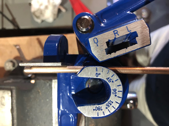
Having cracked the flaring operation I moved onto advanced bending and discovered some issues with the pipe bender that I had purchased. The tool is actually made by Eastwood (a US company) and is marketed specifically for bending brake and fuel hard lines from 3/16" to 3/8". Actually, the three channels in the tool are actually sized for 1/4", 5/16" and 3/8" and the instructions simply state that for bending 3/16" to use the 1/4" channel. All well and good but there is quite a difference in diameter between 3/16" and 1/4" (4.76mm vs 6.35mm) and 3/16" pipe sits very loosely within the bending channel and does not align properly with the 'stop edge' on the tool. I ended up inserting an offcut of 2mm steel sheet between the pipe and stop edge while bending to get the pipe alignment correct in the tool.
 |
3/16" Pipe does not sit square against "stop edge" (circled)
|
 |
Using 2mm Steel spacer to correct pipe alignment in bending tool
|
Making a bend in a piece of pipe is as simple as inserting the pipe into the appropriate channel on the tool and supporting one end by the stop edge (with optional 2mm spacer...), aligning the zero degree marks on the stationary arm and rotating arm of the tool and then pulling the rotating arm around until the zero mark on the rotating arm aligns with the desired angle mark on the stationary arm. Again when working with 3/16" tubing it is not possible to align the zero marks properly, and so bending to a specific angle actually requires a bit of guesswork and frequent checking with an angle finder/protractor.
 |
Misalignment of Zero marks with rotating arm seated on 3/16" pipe
|
 |
Rotating arm pulled round to bend pipe just beyond 45-degree mark...
|
 |
...however, bend is actually not quite 45-degrees
|
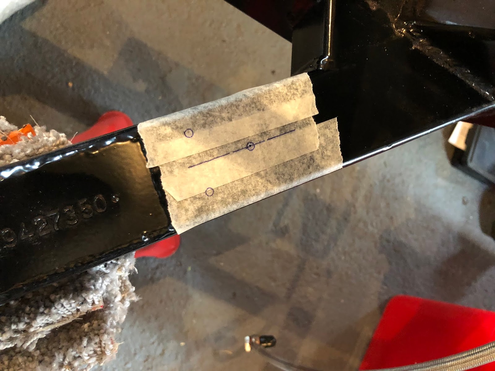
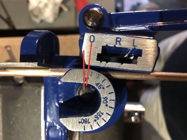
Now, this method is fine if you know where the start of any bend is on the pipe (i.e zero mark corresponds with the start of the bend). But if you are measuring out a pipe run with multiple bends it is easier to measure the position of the bend vertices (the point where the two legs either side of the bend intersect) and then perform the bend utilising the other marks (R and L) on the tool. And at this point, I have another issue with the Eastwood bending tool.
Clearly, at some point, the specification of the tooling has been changed, as the instructions show photos of a version of the tool with cast markings on the rotating arm and clearly identifying the marks to use for the different pipe diameters. The version of the tool I have appears to have engraved marks and has no markings at all for the 1/4" channel (which in any case would still not be quite correct for bending 3/16" pipe anyway). I ended up interpolating the marks for 1/4" by scoring a line extending from the 5/16" and 3/8" marks and using these as an approximation for bending the 3/16" pipe.
 |
Eastwood instructions showing cast marks for all pipe sizes on rotating arm
(Photo courtesy of The Eastwood Company) |
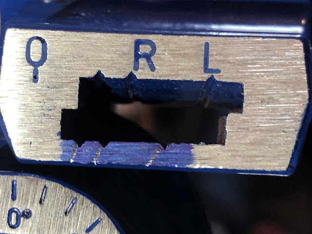 |
Extrapolated lines for 1/4" channel - unmarked notches are assumed to be the 45-degree mark (still needs some guesstimation for 3/16" pipe)
|
I suppose this is all a question of 'you get what you pay for" and let's face it, the Eastwood tool was a shade over £20 and a professional quality single diameter tube bender from an outfit such as Swagelok is way north of £100 which, for a single build, is just not a consideration.
So with flaring and bending techniques now sorted, it's time to make up all the necessary pipes for the Cobra.