Showing posts with label Electrical. Show all posts

Sunday 10 March 2024

Couple of Minor Jobs - Part 2

I have finished off a load of small jobs that are not really worthy of a post all of their own.

The first was to add an earth strap between the engine and the chassis.  Just to be on the safe side I bought a 50mm2 earth cable (which should cope with 345 Amps), with a 10mm lug on each end from PCS Cables.  This was bolted into a convenient hole in the engine block at the nearside front.  I drilled and tapped a hole in the top of the chassis rail and ground off a bit of the powder coat to ensure a good contact.

Engine Earth Strap 

I also put the final hose finisher on the crankcase breather hose.  The hose finisher that I originally bought is still hiding in the garage somewhere, probably hanging out with a 10mm socket, and laughing at me.

Breather hoses completed!

I have given the front of the radiator a couple of coats of Eastwood Radiator paint in satin black.  The bare aluminium finish was not quite in keeping with the "stealth" look that I have in mind for the finished car.  I should have done this before I installed the radiator onto the chassis, but I managed to mask up most of the front with newspaper and a couple of old blankets to protect everything from any over-spray.

Radiator masked up prior to painting...

...and after painting and masking removed

I have also added oil to the rear differential and the gearbox as it is far easier to do this while access is good rather than leaving (or forgetting) until the body is on.

I bought 2 litres of Castrol Transmax oil which is specially formulated for limited slip differentials and used a funnel and a length of clear PVC tube to fill the differential with oil.  I managed to get almost all of the 2 litres into the differential before the oil started leaking back out of the filler oil.

Differential oil

Funnel and PVC pipe filling arrangement

For the gearbox, I bought 3 litres of Motul Dexron III oil which is the recommended fluid for the Tremec T56 transmission.  I used the same funnel/pipe setup to fill the transmission and again managed to get almost all of the 3 litres in before the oil started weeping out of the filler hole.

Transmission fluid

Filler hole for T56 transmission

I also have finally got around to welding up the various threaded bungs I have added to the chassis for the fuel tank, gearbox and exhaust mounts.  I treated myself to a day welding lesson at The Machine Shop to try and get the hang of TIG welding. I'm still not "stacking dimes" but at least I managed to master the art of getting a bit more heat and penetration into the welds.  As the body will sit on most of the locations of these bungs, I ground them down flush to the chassis rails and then treated them to a couple of coats of POR15 rust preventative paint.

Powdercoat ground off around area to be welded

A dodgy stack of dimes...

...after grinding welds down...

...and after two coats of POR15


Tuesday 30 May 2023

Engine & Gearbox Installation - Part 6 - Ancillaries

With the engine in the car, the last job to complete the installation was to attach the alternator and the power steering pump and fit the serpentine drive belt.

When I bought the engine, Kyle supplied a nice billet aluminium bracket set-up, which once I worked out which holes on the engine it was all supposed to bolt up to, went on quite easily.  There is a smaller bracket which supports the rear of the alternator which sits directly against the cylinder head, the larger front bracket is then set off from the engine block with a number of spacers.

Initial Fit of Ancillary Bracket

Somewhat oddly, despite it being listed as a part of the bracket kit, I didn't seem to have the lower idler pulley with my kit; it was all blister packed and there didn't seem to be a "missing" spot for it.  That created a short delay in proceedings as I had to order a new idler pulley from Summit Racing in the States (I did this to be sure I got the right one, which needed to be for a Z06 Corvette).  Once it arrived it just needed to be fitted with the 110mm M10 bolt supplied with the bracket kit through the pulley and a couple of spacers and screwed into a hole in the engine block.

"Replacement" Lower Idler Pulley

The alternator could then be fitted into place between the front and rear parts of the bracket and held in place with two M10x80 bolts.

The alternator is fixed in place

Then it was 'just' a matter of fixing the Power Steering Pump in place with the three M8x25 bolts supplied.  And with that, a five-minute job turned into a several weeks job...

The first problem was that the Power Steering pump that I had been supplied with the engine, which was a standard GM / AC Delco unit, did not have threaded mounting holes.  The fixings were meant to be much longer bolts that passed through the whole unit and were secured with nuts at the rear.  OK, so I could have bought some longer bolts, but the pump unit is a snug fit between the front and rear parts of the ancillary bracket which would have made it impossible to get any nuts on the bolts in any case.

Another AK builder, who had also got his engine from Kyle, and with who I had been in contact previously, had purchased a new pump from Summit and he had previously given me the details of this.  Figuring he might have encountered the same problems that I was having, I blindly went and ordered the same pump; a performance pump with AN fittings from Tuff Stuff.  This was a long-lead item from Summit and I had to wait several weeks for it to arrive.  Once it arrived, I was relieved to find out that it did have threaded mounting holes and managed to fix it in place on the bracket.

Tuff Stuff 6170ALB-2 Power Steering Pump...

...installed in place

At this point, I noticed my next problem.  The pump that I ordered has the outlet port on the bottom.  This is the high-pressure line and while I knew that I would need to get a new hose made up with an AN fitting to suit, it was pretty obvious that there was going to be insufficient room between the port and the bracket to accommodate an AN fitting and sufficient clearance to form a 90-degree bend (similar to the brake pipe in the picture above, you can not form a bend immediately behind the fittings; there will need to a certain straight length needed to allow the pipe bender to do its thing...).  This was confirmed in my discussions with Adam at Earls, who I had contacted to request a quote for a new high-pressure pipe.

I had two solutions.  Grind away part of the bracket to give clearance for the fitting or find another pump.  I went with the latter option but this time did a bit more research before pressing the order button. I thought a pump was a pump, but reading through the Tuff Stuff catalogue online, there are loads of configurations.  So this time I bought a pump with a top outlet and with threaded mounting holes and with AN fittings.  Summit was showing out of stock so I ordered via Ebay.com but that still took another 8 weeks to arrive!

Does what it says on the box...

...only this one has a top-facing outlet port!

The power steering pulley needs to be installed onto the pump using a special tool.  It's a press-fit but should not be attempted using a hydraulic press as that could damage the pump.  I bought a cheap tool from Amazon; this is basically a threaded bolt that screws into a thread at the end of the pump drive shaft with a nut/flange arrangement threaded onto the bolt.  The flange sits on the face of the pulley and then by holding the main bolt with one spanner and winding the nut down with another spanner, this presses the pulley onto the shaft.  The pulley is installed until the end of the shaft is flush with the front face of the pulley.

It's probably obvious, but the pulley needs to be installed with the grooved flange to the front; this is to allow a puller to grip onto the pulley in the event that it needs to be removed.  If you install it the wrong way around, you will need to take it to your local helpful mechanic to get it removed while he laughs at you; ask me how I know this...

Holley Power Steering Pulley - note which way round it goes...

Pressing the pulley into place...

...until the face end of the shaft is flush with the front of the pulley

I could then install the pump back onto the ancillary bracket; it needed a bit of wriggling to get the pump with the pulley into place with the tubular bracing of the AK Gen III chassis.  I could then get the bolts into place and tighten them to 15ft-lbs / 20Nm.

Finally, the pump is in place!

(Actually, I did have to take the pump out again as I had forgotten to torque up the bracket mounting bolt that is cunningly obscured by the pulley once the pump is in place.  I torqued all the bracket bolts to 25ft-lbs / 34Nm.)

Finally, I could get the serpentine belt looped onto the alternator, power steering pump, water pump, idler and crank, and using a spanner to pull the belt tensioner forward, slipped the belt fully into place and released the tensioner.

The serpentine belt looped into place...

...and over belt tensioner.

With all the faffing around with power steering pumps, that little job only took the best part of five months!!!


Thursday 27 October 2022

Gearbox Part 3 - Electronics!

Back in the good old days, a manual gearbox was a simple matter of some magic mechanical coggery hidden in a case, with an input shaft, an output shaft and some sort of shifting mechanism to change between the (then four) gears.

Clearly, things have moved on, and not just in the number of available gears.  After unboxing my Tremec T56 gearbox I noticed a number of electrical connectors dotted around the casing.  After some internet research, I discovered the following:

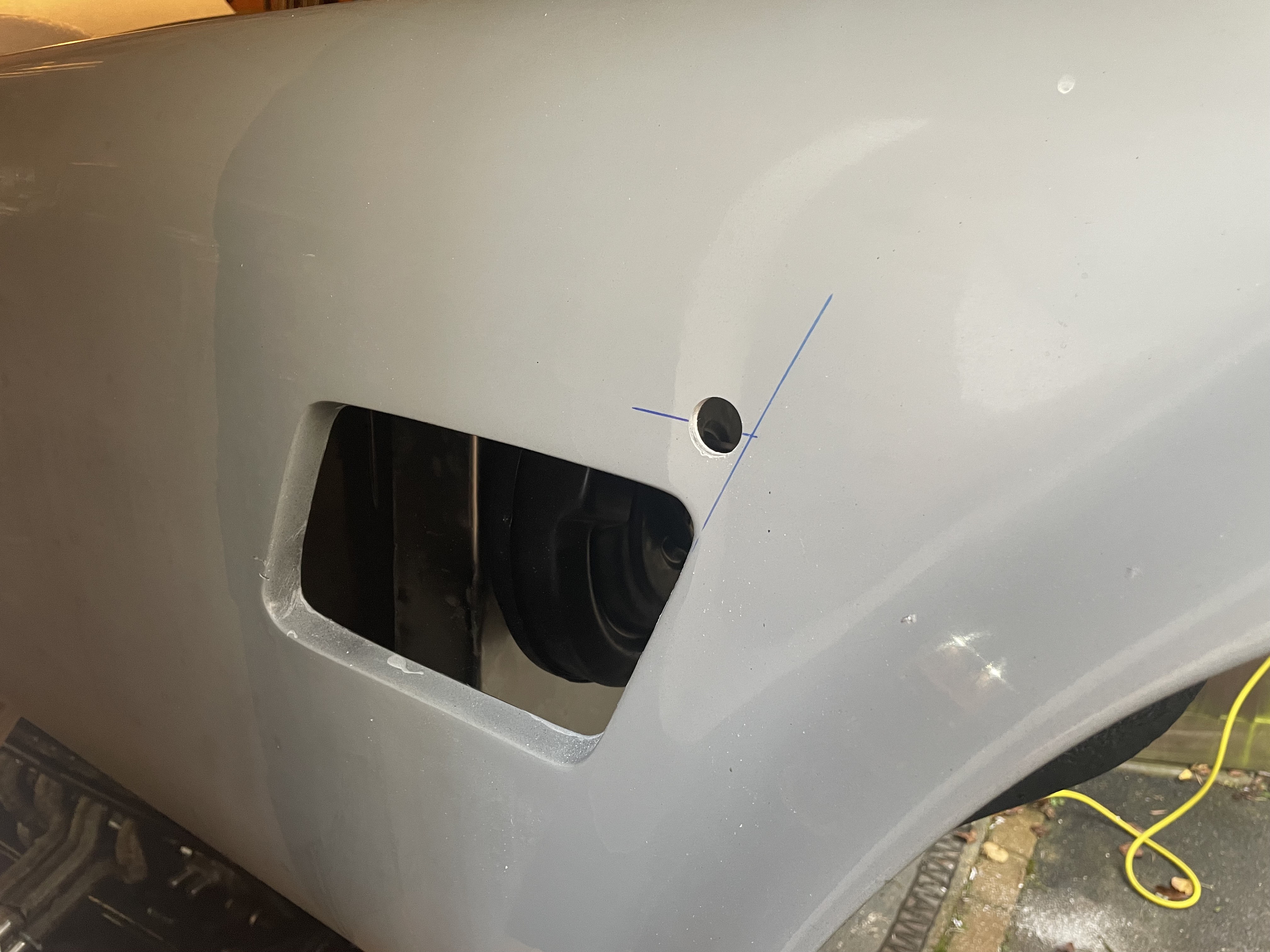
The connector at the front left-hand side of the gearbox casing is for the reverse light switch i.e it activates the reverse lights when reverse gear is selected.

Reverse Light Connector

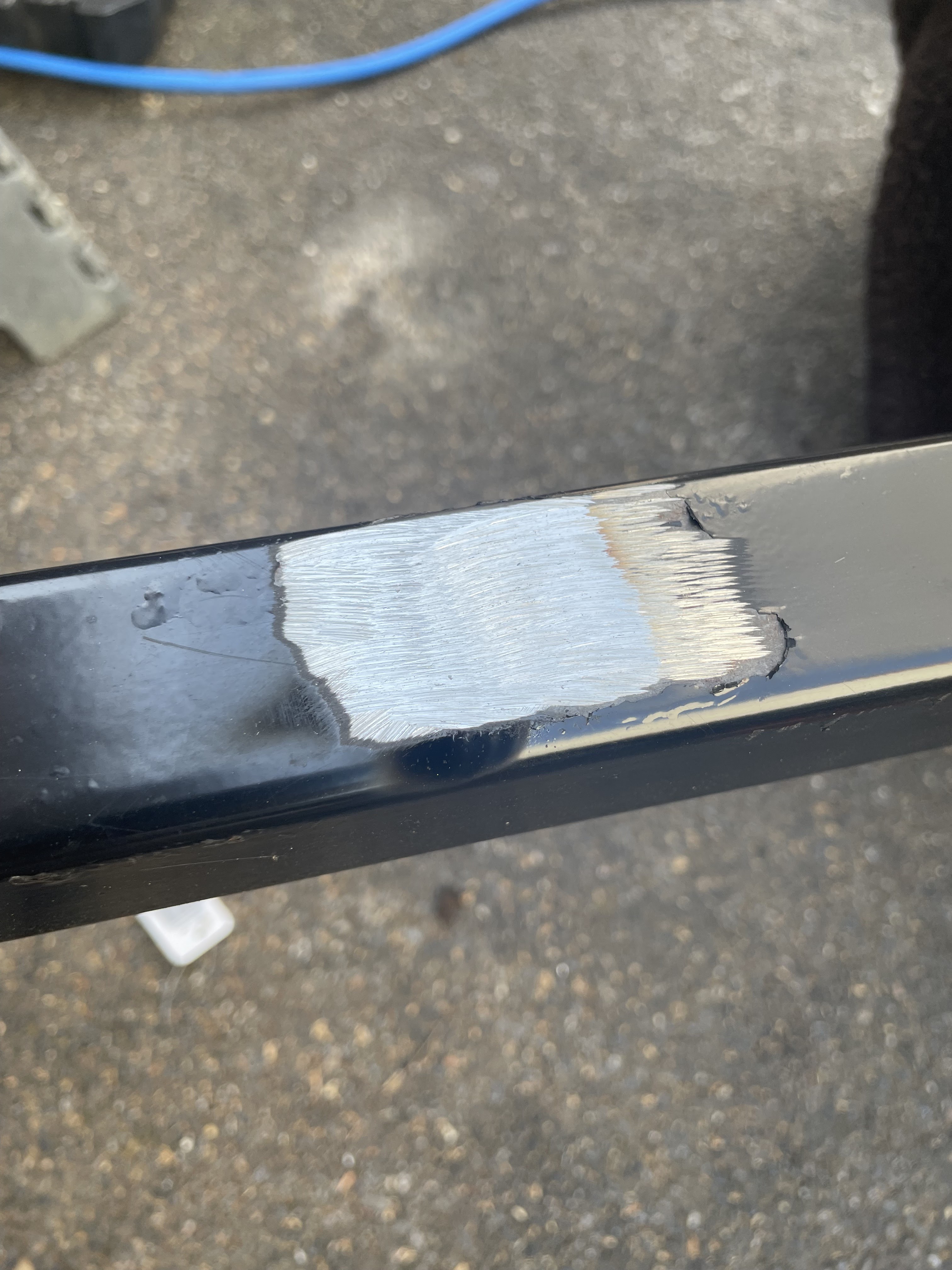
The connector at the rear left-hand side of the casing is the VSS output (variable speed sensor) which is used to send a signal to an electronic speedometer (there is also a mechanical speedometer output on the opposite side to the VSS connector - as I will be using the VSS option the mechanical output needs removing and replacing with a blanking cover).

VSS Output Connector

Mechanical Speedo Output (will be removed)

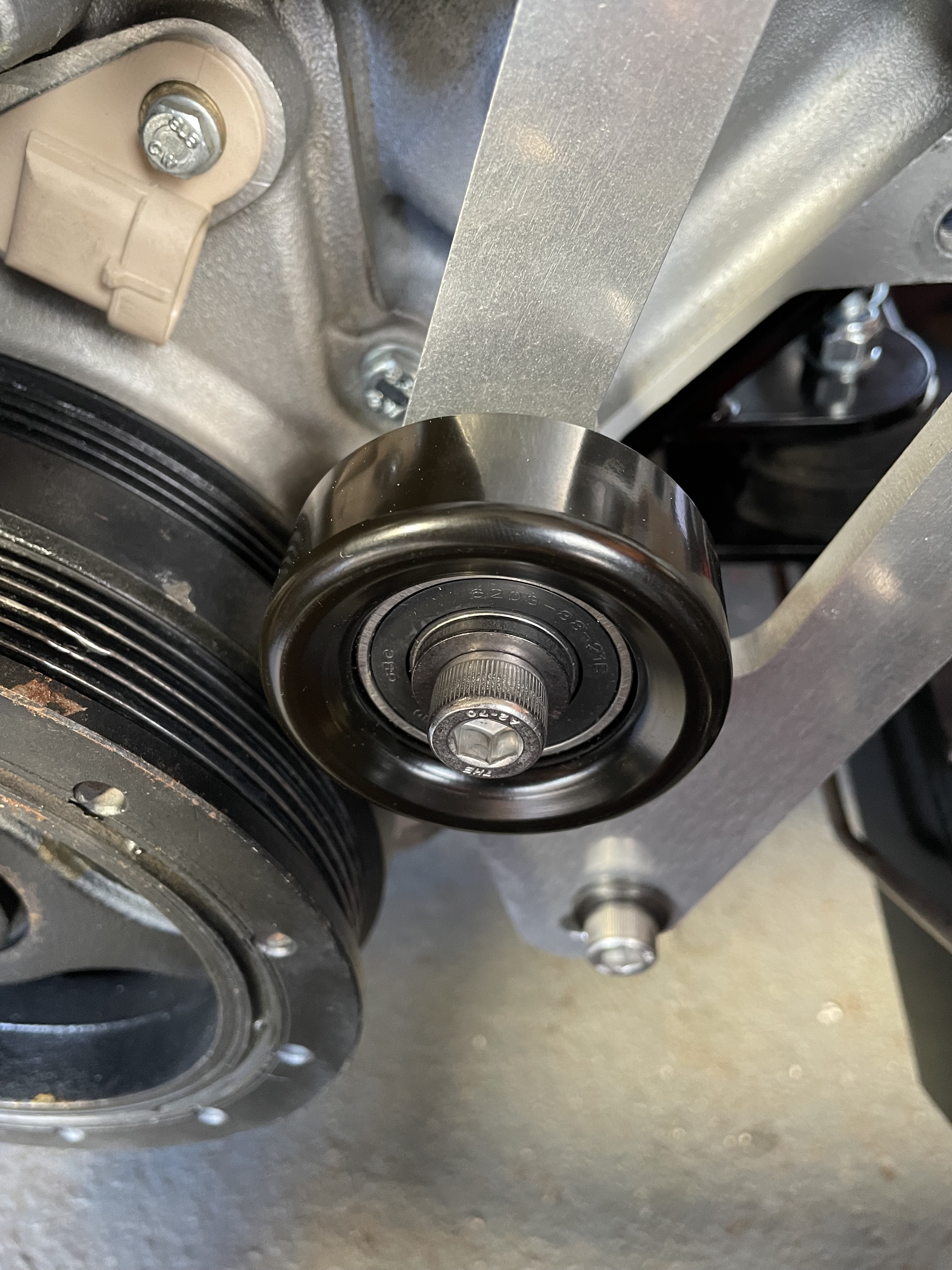
Finally, the connector at the rear of the casing behind the shifter location is for the reverse lock-out solenoid.  This is a safety feature and prevents inadvertent selection of reverse gear while the car is travelling forward at great speed; on production cars the solenoid is automatically controlled by the car's ECU to only allow reverse to be selected when the car is stationary.

Reverse Lockout Solenoid Connector

So how to control the reverse lockout solenoid?

The reverse lock-out is apparently just a spring with a ball-bearing detent.  This can be overcome with brute force but clearly is not recommended by Tremec and could lead to damaging the gearbox.

Other solutions suggested involve the use of a microswitch on either the clutch pedal or brake pedal to operate the solenoid - on the basis that you would probably have your foot on one or the other or both when preparing to select reverse gear.  The downside is a) the solenoid would operate every time the brake or clutch pedal was pressed so possibly leading to premature wear and failure and b) if the brake or clutch pedal was pressed at 100mph (not unlikely) the solenoid would operate and so it would still be possible to select reverse gear at a high forward velocity, which kind of defeats the object of having it in the first place...

There are several aftermarket manufacturers of a small black box of tricks which simply does the job of the missing OEM ECU and, using the VSS output, will only activate the solenoid when the car is stationary or travelling very slowly (typically less than 3mph).  This would probably be the most sensible option.  The downside is that these kits cost several hundred dollars (plus good old import duty and shipping).

Fortunately, the CANEMS ECU that I bought as part of my engine package does have the ability to be programmed to operate a switched output based on the VSS output i.e to only operate the solenoid when the car is stationary.  Will need a bit of loom surgery to accommodate but in theory, all looks quite straightforward.

The final piece of this story is to obtain the various electrical connectors to join up with those on the gearbox.  I bought a kit from Bowler Performance Transmissions in the States; this included all the various connectors each with a short wiring pigtail and a billet blanking plate and bolt for the mechanical speedo output.  I ordered online and was quoted some ridiculous price for shipping (more than the price of the kit) but when I rang Bowler they were able to come up with a far cheaper shipping method.

Contents of the Bowler T56 Install Kit

So looks like I will have some fun when it comes to trying to add these into the wiring loom later but for now, I can get cracking on hooking the gearbox up to my engine and getting closer to installing it in the chassis.