Tuesday 26 May 2020

Rear Axle Strip Down - Part 7 - A Fatal Extraction

With the rear hubs now all nice and shiny after their trip to the sandblaster, it was time to tackle one of those tasks I was not looking forward to.

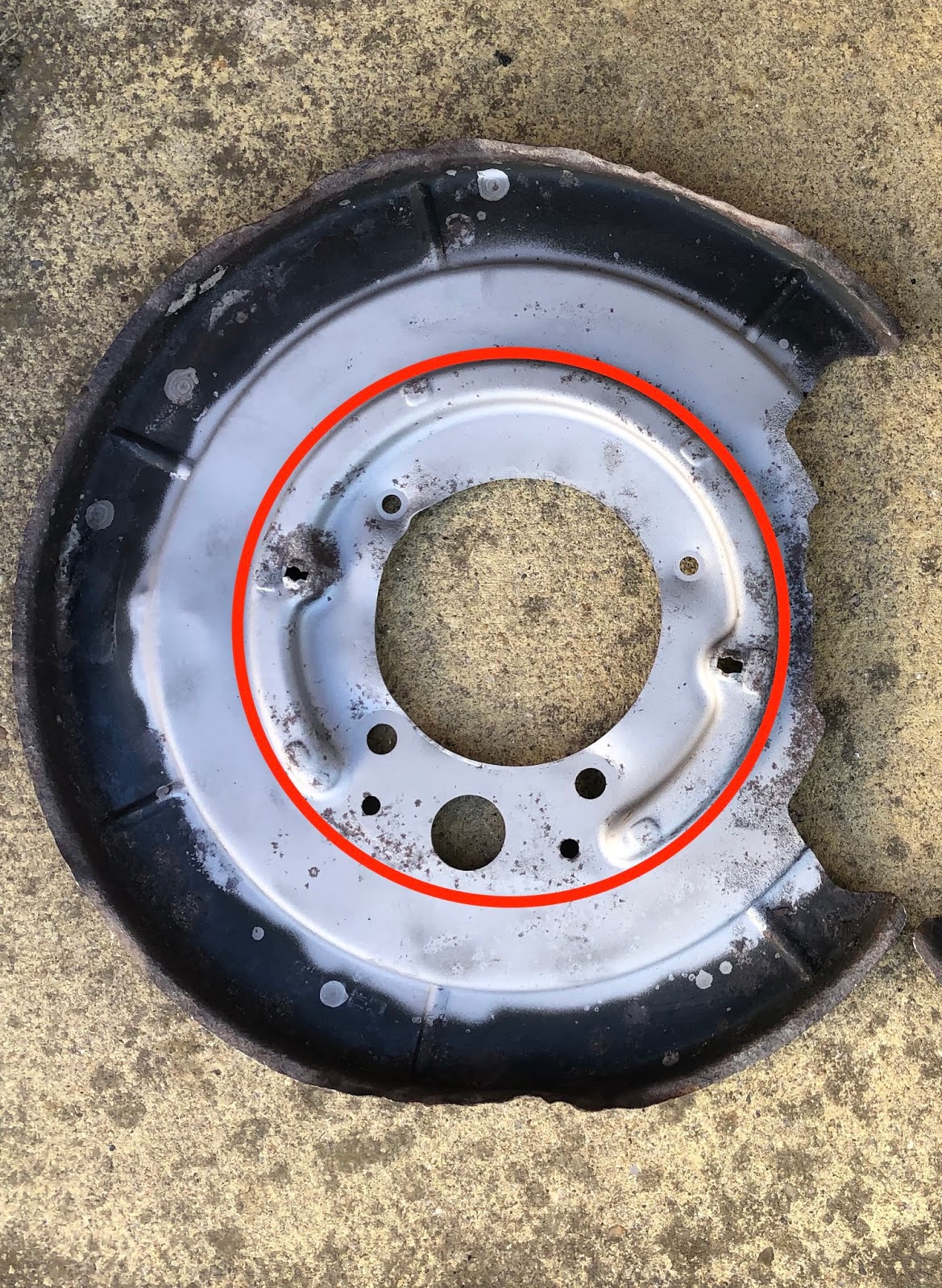
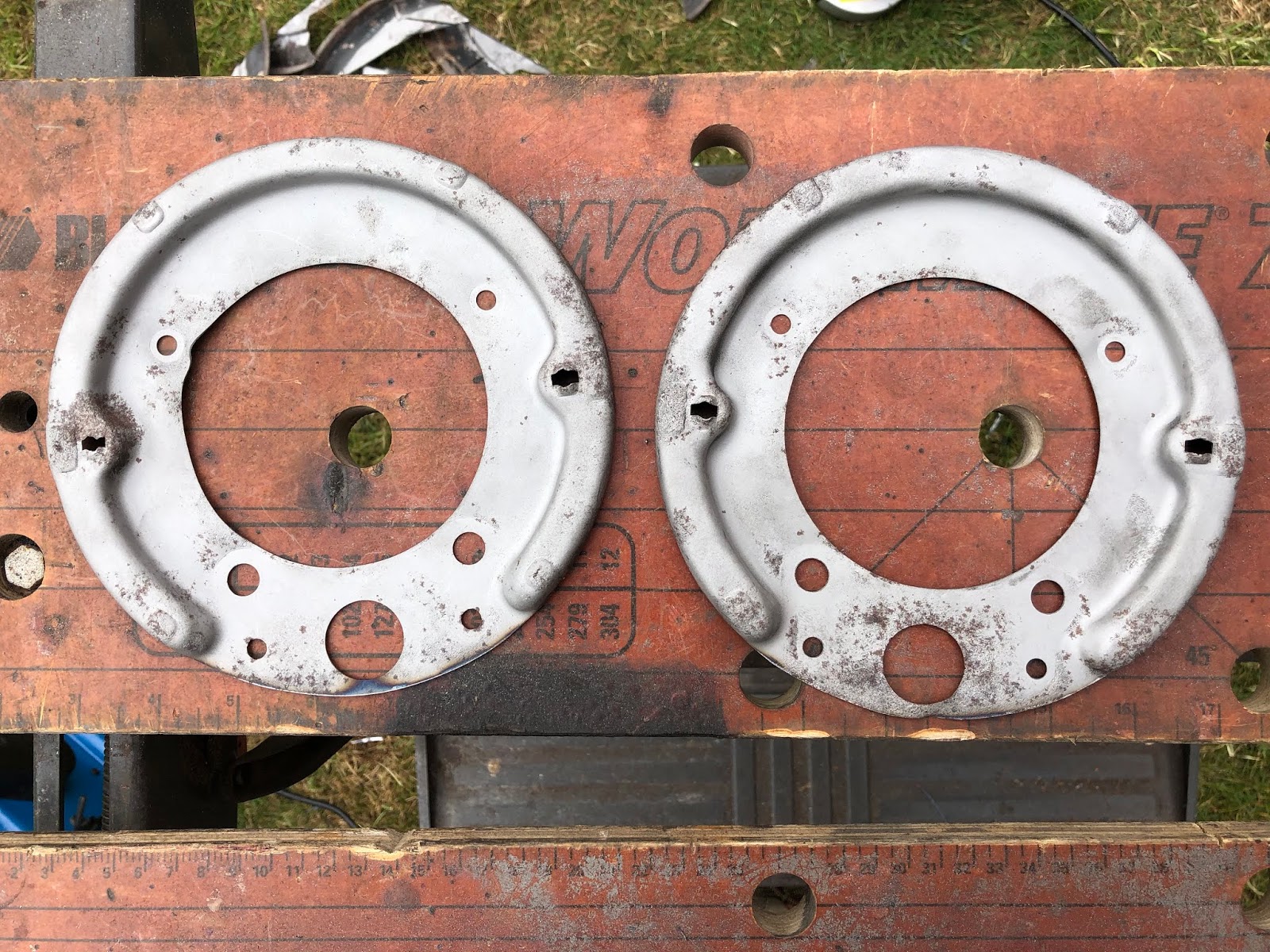
When stripping down the rear hubs, the heads of the two smaller screws securing the brake backing plate to one of the hubs had sheared off.  Now it is time to attempt to remove the remaining parts of the screws which are still stuck in the hub.


Today's mission - removal of two sheared screws...

There are many suggested ways, it seems, to remove broken screws and bolts.

The most straightforward would have been to position a suitable sized nut over the top of the sheared-off screw and using a hot metal glue gun, blob some weld into the middle of the nut to join it to the screw.  Then it should just be a matter of using a spanner to undo the nut/thread combo.  My only issue with this was that the sheared-off thread is just below the surface of the hub and, while the theory is that the steel weld won't stick to the aluminium of the hub, I wasn't prepared to take that chance with my hub.

Next on the list of discarded options was the use of a suitable sized screw/stud extractor.  The theory behind these is that a pilot hole is drilled into the broken screw into which the extractor is inserted; the extractor has some reverse cut threads that bite into the metal and undo the screw.  Now I have never had much luck with using screw extractors even on screws in wood with chewed up heads.  And given that these broken screws had resisted all attempts to remove them initially before breaking, including heat, impact screwdrivers and penetrating oil, I seriously doubted that using an extractor was suddenly going to persuade these screws to give up their grip on my hub.

So the method I decided upon was to slowly try and drill out the broken screws, using drill bits of increasing size until the hole is drilled out to the diameter of the screw shank and then to retap the hole with the required thread size.

Of course, I should have known it was never going to be quite that simple.

The first problem is that actually trying to centre punch the end of a sheared-off screw is quite difficult - the broken surface was uneven which made it hard to locate the punch in the exact centre. In hindsight, I should have used a Dremel or similar to grind the end of the screw flat before using the punch...

The second problem was that smaller diameter drill bits are very short, the chuck on my drill is quite large and the offending holes are very close to the hub bearing housing; the result that I could barely get any depth to my initial pilot holes in the screws using a 2mm bit.  Worse to get any depth I had to fix the drill bit with only a very short length of the shank actually in the chuck.  This means that the drill bits are very flexible and the end is prone to wander (of course compounded by the difficulty of punching the centre of the screw in the first place).


Drilling depth restricted by the clash of the drill chuck and the hub...

The end result was that the pilot holes on both screws did not really start off on centre so by the time I started opening the holes up with 3mm and 4mm bits it was clear that the holes were going very awry.  The other issue is of course that with the hub being aluminium the drill bits found it much easier to slip off the hard steel surface of the screw and chew their way through the softer aluminium.


Opening up initial pilot holes...

By the time I got to the 5mm bit, I realised I needed a Plan B, as the result was that I was drilling out about 3/4 of the area of the screw and the rest of the hole was through the aluminium hub.

Plan B was to use a Helicoil kit (thanks to that well known on-line retailer and their next day delivery service).  Helicoil inserts are a threaded metal insert used to repair stripped threads; the stripped hole is drilled oversize and tapped for the metal insert which is then inserted into the tapped hole to reinstate the original thread.

My logic for this approach was that by drilling the hole slightly oversize for the Helicoil that this would allow me to remove all the remaining portion of the screw thread from my misaligned drilling.


Helicoil Kit - includes drill, tap, insertion tools and a selection of inserts

The hole in the hub should be an M6x1.0 thread so the first step was to drill out the hole using the supplied drill bit for the corresponding insert.


Prior to drilling - misaligned attempt to drill out screw is clearly visible!


After drilling - operation didn't quite clear out all of the remaining screw

Next step is to tap the holes for the Helicoil inserts using the tap provided for the M6 inserts.


Tapping holes for inserts.  During...


...and after

Next stage is to insert the Helicoil.  The inserts have a small tang on the bottom of them which is inserted into the slot on the appropriate sized insertion tool.  This is then used to twist the insert into the threaded hole until the insert is approximately half a turn below the surface.  Care needs to be taken to allow the insert to thread itself into the hole without applying too much downward pressure.  My first attempt unwound the bottom of the insert... Fortunately, it was not too far into the hole and I managed to extract it without too much excitement.


M6 threaded insert in place on the insertion tool

The final step is to use the punch supplied with the kit and a sharp tap with a hammer to break the tang off the bottom of the insert.  


One repaired hole!

Replacement screw fits perfectly!

In the end, it was not as traumatic a job as I was expecting it to be (although equally, it was not a simple as I would have hoped...).  Both holes are now repaired albeit both are slightly off from where they were originally.  Hopefully, the brake backing plate will still line up - if worst comes to worst I may have to slightly oversize the holes in the backing plate.

Right, time for a cup of tea to celebrate.


Rear Axle Strip Down - Part 8 - Trimming Rear Brake Backplates

Before I can start reassembling the rear hubs there are a couple of components that I still need to clean and fettle.

I had completely forgotten about the ABS sensor rings that press onto the rear of the hub axle.  These were still in my box of removed parts.  These just needed the usual clean up, sandblast and powder coat to get them ready for reassembly.


Before and after cleaning and sandblasting...


...and after powder coating

The other components that needed attention were the rear brake backplates.  To be honest I had been putting these off a while.

The original XJ40 backing plate covers the whole of the rear disk with a slight lip that wraps around the edge of the disk.  In the AK set-up, it is recommended that the backing plate is trimmed down, although there is no guidance in the build manual on how far to trim (and the picture in the manual is based on an older style backing plate and not the XJ40 type that I have).

The backplates that came with my donor axles had, frankly, seen better days and the edges of the plates were rather chewed up and had succumbed to an attack of rust - although in theory given that the plates need to be trimmed this was not, initially, a concern.

XJ40 style brake backplate - this is the better of the two...

The first step was to give the plates a clean-up and see exactly what I was dealing with.  I gave them both a quick brush off to remove loose dirt and grime and then gave them a bath in some citric acid solution for a couple of days to remove as much rust as possible.  Given the size of the plates and my bucket, I could actually only immerse half of each plate in the acid solution at a time - but that was enough to see that I had a problem.


After half an acid bath - tidemark is clearly visible

It was obvious at this point that the lower plate in the above photo was generally sound including around the handbrake shoe mounting points.  The upper plate, however, was showing signs of tin worm in some critical areas around the lower brake shoe mounting block.

Signs of tin worm...

This corrosion was well within the area of the backplate that I figured needed to be retained after trimming, so this was not a good sign at all.  Holding the plate up to the light confirmed that there was even more bad news, with evidence of the dreaded rot around the handbrake retaining pin mounting holes as well.

Only one of those holes is supposed to be there...

The other side is not much better...

I was already concerned that the retaining pin holes were oversized and were likely to require some cunning plan to fix them to be able to hold the pins - but this discovery basically confined this backing plate to the scrap bin.

I dropped Ben at Simply Performance a note to see if he could send me a replacement pair of backplates.  I have to say I can't fault the customer service of Simply Performance one bit.  They guarantee that all the donor parts they provide can be refurbished and reused.  There's no quibbling over this and again, in this case, Ben said he would pop a couple of replacements in the post and, sure enough, two new(er) backplates arrived a couple of days later.  Ben had even sandblasted the centres of the plates to check that there was no rot present. That is service!

Shiny 'new' brake backplates courtesy of Simply Performance

The replacement backplates came without the lower brake shoe mounting blocks in place so I needed to remove these from my original components.  Following the dip in the acid bath, undoing the two bolts that secure each block was relatively straightforward.  On the rear side of the block, there is an additional cable guide formed from a short section of tube brazed to a (very) thin plate.  Again on the more corroded original backplate, this plate had been reduced in thickness to practically transparent.

Brake shoe mounting block and rear cable guide after removal

Finally monsieur - a wafer-thin mint!

I consulted with my local fellow AK builders Richard and Dave.  Richard had elected to keep this guide plate on his build on the basis that it gave a smoother path for the handbrake cable.  Dave had his backplates trimmed down by AK and they were supplied without the guide plate; the conclusion is, therefore, that it's optional!


Backplate installed with handbrake cable - Photo courtesy of Richard Chippendale

I kind of concur with Richard's view that it assists with the routing of the handbrake cable but it seems a bit odd that the guide tube leaves a part of the handbrake cable exposed.  For the moment I think I will proceed without using this component; although maybe later might consider fabricating a replacement plate with a longer tube to cover the full path of the handbrake cable in this area.

So the next job - the one I hadn't been looking forward to - was to trim the backplates down.  As noted above, the AK Build Manual doesn't really give any guidance in this regard.  But thankfully Dave sent me a couple of photos of his which had been cut down by AK.  

Cut down backplate as supplied by AK - photo courtesy of Dave Rich

So basically the plates need to be trimmed back to the edge of the raised circle as shown below.  Luckily I now have a couple of spares to practice on, so out with the angle grinder!


Extent of the backplate to be trimmed

Using a cutting disk I trimmed close to the edge of the raised flange.  I then switched to a grinding disk and took the excess steel back flush with the edge of the raised flange.  

Initial trimming with grinder...

First pass of trimming complete...

Edge dressed with grinding disk

Feeling pretty pleased with the trial run, I took a deep breath and took the angle grinder to the two replacement backplates!  I followed exactly the same technique as for the trial run, but finished off the edges after the grinding disk with some gentle filing and then a touch of linishing on the belt sander to remove any sharp edges and to make them super smooth.


Final cut-down backplates

I was quite happy with the final result and it wasn't as traumatic an operation as I had feared.  I treated the backplates to a quick sandblast for a final clean-up as well as the brake shoe mounting blocks before another session with the powder coat gun!


Looking better than when I started!
Brake shoe mounting block was treated to the candy red powder coat!

With those jobs done I am now very close to being able to start reassembling the rear hubs.

Sunday 10 May 2020

Virtual Chassis Construction

Over the winter months, I started teaching myself how to use Autodesk Fusion 360.  The main advantage of this software is that it does a free educational licence version - and being that my son is still at secondary school, I signed him up on my behalf!

I originally just wanted to be able to design a couple of brackets for the Cobra build - but things got a bit out of hand...

I had started to design a bracket to hold the brake pipes and clutch pipe on the chassis leg with some unions to allow the pipes up to the master cylinder to be added later once the body is on (there will be a separate post on this).  

I wanted to see how this bracket would sit on the chassis rail and to check the mounting position.  So I started modelling a portion of the front of the AK chassis...

Then I thought I could use this portion of modelled chassis to check the brake and clutch pipe routing - part of the tubular bracing on the AK Gen III chassis creates a very narrow path for the front brake and clutch lines.  This eventually turned into deciding to model all the brake and clutch pipe routings so I could decide where to put the pipe clips to ensure a maximum spacing of 300mm.

Well over many long winter evenings I managed to model up practically all of the AK chassis - and then spent a few more evenings remodelling some bits of it when it was apparent some of my measurements were not correct.

It's not fully complete - I still have to finish off the tubular bracing parts - but I've included a couple of pictures below.  I've added a sneak preview of part of the chassis with brake pipes and clips modelled - I'll cover this more fully in one of my posts on the fixing of the brake lines.  There's also a part-finished render from Fusion 360 of this section of the chassis (the processing power of my Mac isn't up to getting the full render done!) - let's see if it looks as good when I actually finish it!


Thursday 7 May 2020

Brake Lines Part 1

The routing of the brake lines is relatively straightforward.  The AK Build Manual shows the positioning of the pipe runs quite clearly and most other builders have had no problems with this layout and with fixing the pipes using P-clips or the plastic push-in type clips.

So clearly this is the way to go and it should all be simple, yes?

Well...

Clearly, for me, that would all be too simple...and I lay the blame squarely at the doors of the guys from Bad Obsession Motorsport (BOM).  I have been following their Project Binky build on YouTube for some time; there are several episodes charting their build of a Rally-spec Mini based on shoehorning the running gear from a Toyota Celica GT4 into the confines of the Mini.  These guys are evil geniuses when it comes to bespoke bracketry (of which their project required many) and when they imposed a "no P-clip" policy on the build and fabricated their own brake/fuel line clips, I started to get thinking.

The AK chassis is a thing of beauty.

 OK, maybe I'm getting carried away. but the chassis rails are all box section and fully sealed.  So why would I want to drill loads of holes into the chassis providing potential entry points for water and the risk of the dreaded metal rot?  I could inject Waxoyl into the box sections to mitigate this but surely it would be better to avoid the holes in the first place.

The BOM solution consisted of a steel plate, a couple of rivnuts and some 12mm thick nylon sheet; the resulting component can secure multiple pipes replacing several P-clips.  A CAD model of the basic concept is shown below.


Over-Engineered P-Clip Replacement Concept...

The steel plate, with the rivnuts welded in place, is welded to the chassis, the two halves of the nylon clamp are then placed over the rivnuts, bolted down and voila!  One pipe clamp with no drilling into the chassis rails.

After much mulling over this solution, I realised that I was probably being a bit anal about this.  On close inspection, there are already several holes drilled in the AK chassis for the body mounting bolts amongst other things.  I will also probably be unable to avoid drilling some holes for mounting the 3-way brake unions and eventually for mounting the fuel pump and filter.  Additionally welding the mounting tabs onto the chassis will involve removing some of the powder coat and having to try and recoat the patches, plus some welding into some tight spots between the chassis rails; which to be honest, sounds like a lot of faff (even for me).

(And actually by the time I have posted this I will have drilled a load of holes in the rear of the chassis for the fuel tank mounting...)

So maybe the answer is to bolt the clips to the chassis after all; in which case why not just use P-clips?  However, I still think the bespoke solution is quite neat and does have the advantage that I can use a single clip to hold multiple lines (including potentially the fuel lines) so that does reduce the number of holes that I will need to drill.

So with a slight modification, Version 2 of the P-Clip replacement concept was produced in CAD.


Version 2 - spot the difference!

The next step was to make a prototype based on the CAD concept.  The mounting plate was cut from a spare piece of 2mm sheet steel.  I drilled two 7mm diameter holes which were countersunk to accommodate two M5 rivnuts and allow the rivnuts to sit flush with the back of the plate.  A 5mm hole was drilled for the mounting bolt.

The clip body was made from two pieces 12mm thick Nylon-6 sheet cut 12mm wide.  The bottom piece had two 7mm diameter holes drilled to sit over the rivnuts and a 10mm counterbore 5mm deep to accommodate the head of the mounting bolt.  The top piece was drilled with two 5mm diameter holes with a 10mm counterbore 5mm deep to allow the heads of the fixing bolts to sit below the surface of the clip.

The final step was to hold the two pieces of the clip together and drill a 3/16 diameter hole and a 1/4 diameter hole (for brake and clutch pipe respectively) along the join line between the two halves.

All the components for the brake pipe clip...
M5 Rivnuts in place on mounting plate - large counterbore in bottom half of clip is for cap-head bolt
Bottom half of clip in place on mounting plate
Top half of clip in place - secured with M5 x 16 Cap-head bolts
Completed assembly - holes for 3/16 brake pipe and 1/4 clutch pipe
Rearview with M5 x 6 Cap-head bolt in place for securing to chassis

I'm pretty pleased with the prototype so now I just need to knock out a few more in various configurations depending on fixing location and pipes that need to be secured.

To be honest this is completely unnecessary and massively OTT compared to the perfectly adequate and usual methods of fixing brake pipes.  But it's another little way of putting my own stamp on this build.