Friday 14 December 2018

Bush Removal!

The title of this page should generate some internet traffic......

Since AK supply new suspension wishbones all round, there is no real need to remove any of the bushes from the front wishbones when stripping down the front suspension.

The only bushed parts that need to be reused are at the rear - being the "pendulum" and the wishbone tie, both of which support the rear lower wishbones and the differential unit.

I had assumed that new bushes would be required all round as a matter of good practice.  However as per my post on the rear suspension strip down I discovered that the bushes in the rear wishbone tie are a non-serviceable item (you can no longer buy them either separately or as part of a replacement wishbone tie part), so DO NOT REMOVE THESE BUSHES!!

So the only bushes that I actually need to replace are in the "pendulum" bracket.


Pendulum bracket

So what is a bush?  In simple terms (?!) it is a sort of vibration isolator found anywhere where there is a joint in the suspension system of a car.  They cushion the movement between two solid parts, helping to avoid shocks and vibration and making for a quieter and smoother ride.

The bushes as fitted to the Jag suspension are of the metalastic type, which consists of an inner and outer metal sleeve with an rubber core in-between.  They are also an extremely tight fit in whichever part of the suspension they are mounted and typically quite hard to remove, especially in older vehicles once rust and road debris have done their bit!

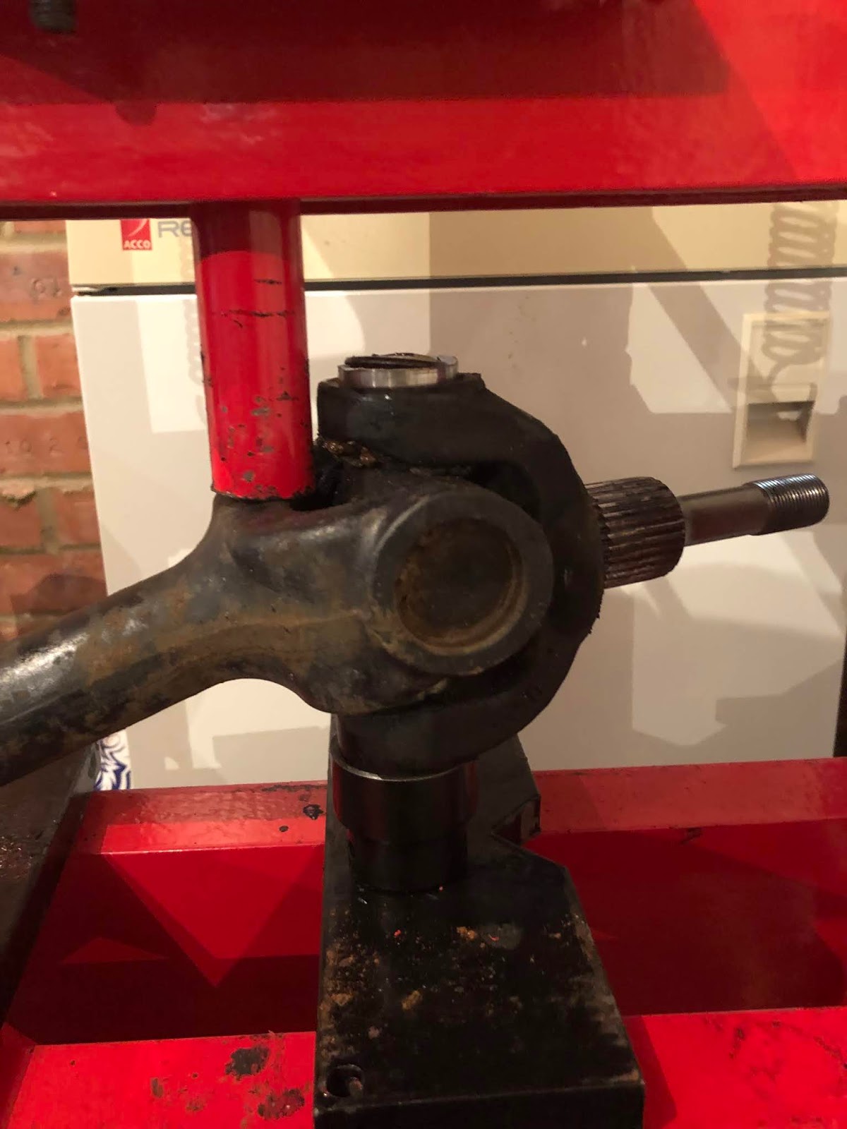
Although I did not need to remove the bushes from the front wishbones, I decided to have a couple of practice attempts in preparation for the rear pendulum.

I am fortunate enough to have a 10 ton hydraulic press in my garage which I thought would be man enough for the job and indeed on my first attempt one of the front wishbone bushes simply popped out with no problem what so ever.  The second attempt was not so successful; having cranked the jack on the press up to what I felt was worryingly close to breaking point, there was no sign of any movement.

Plan B involved using a hole saw with a suitable diameter to cut into the rubber between the two steel sleeves.  This allows the removal of the inner sleeve and then using a cold chisel and a large hammer, one end of the outer sleeve can be hammered inwards with freed the remains of the bearing sufficiently that it could be easily removed with the press.

The one draw back of Plan B is that it generates a lot of smoke and covered my working area with little globules of burnt rubber that stick to everything and are a pain to clean up...

New hole saw (left) - after bush removal (right)

I also found that all the bushes are slightly different sizes which would require the purchase of a large number of different diameter hole saws.  So I needed a Plan C.

In the end Plan C was much the same as Plan A, except that when I reached the point where I thought the press was going to break, I closed my eyes, protected my most valuable body parts, and cranked the jack handle a couple more times!

This generally resulted in an almighty bang - which thankfully was not the press breaking, but the bush shifting in the mounting, after which it pressed out relatively easily.

A naked bush!

Pendulum bracket with all bushes removed


Friday 7 December 2018

Black Friday (Thursday?!) Bargain

Having slightly (?!) grazed the rear lower wishbone inner fulcrum shafts with my angle grinder while trying to complete disassembly of the rear subframe (Rear Axle Strip Down - Part 4, I had reconciled myself to the fact that I was going to have to buy replacement shafts.

Original fulcrum shaft - with "slight" nick
from angle grinder...!

I had previously checked that it was possible to buy these, and while they are available,  original or OE fulcrum shafts are not cheap!  When I checked SNG Barratt had OE items listed on their website at the time for just over £130 - EACH!!!  

This was going to be a significant dent in my planned expenditure.  However I have to thank another fellow Cobra builder, James, who having read my blog, got in contact to tell me that he had spotted that SNG Barratt had discounted the fulcrum shafts by £113 - so they were only £20 each!  

Needless to say I got straight onto the SNG website and ordered two - saving myself £226.  That's my Black Friday (Thursday) bargain for the year.  Excellent service from SNG; I ordered them yesterday lunchtime and they arrived today. Happy days!!


£266 worth of fulcrum shafts - for the bargain price of £40!


Project Snake goes Global!!

Sometimes the power of internet amazes me (and scares me in equal measure!).

Last weekend I was browsing Facebook and found the AC Cobra group page - which although mainly for owners of real AC / Shelby Cobras, is also open to owners of replicas and generally anyone with an interest in these amazing cars. Once my request to join the group had been accepted I posted an introduction to the group including a link to my blog.

Since then I have had just shy of 300 views to the blog - in less than a week!  The audience has been from all corners of the earth with views from US, Australia, South Africa and Europe and of course the UK.

So welcome to all those who have taken the time to visit my blog.  I hope its of interest and that you keep coming back to see how the project progresses.  I'd welcome any comments or feedback on the content (I'm a blogging newbie) and of course any tips / advice etc will all be grateful received.

I think I can say that Project Snake has gone global (but not viral....yet!!!!)

Thanks all.

Sunday 2 December 2018

Rear Axle Strip Down - Part 4

The last major part of tearing down the rear axle / subframe was to remove the lower wishbones and fulcrum shafts from the wishbone tie.  This part of the rear subframe can be seen at the top of the photo below.  The 'pendulum' (the rectangular looking bracket at the left) was removed from the front of wishbone assembly by Simply Performance when they removed the diff for refurbishing.


Lower wishbone assembly (top)

As has become usual with stripping down the rear, this was not as straightforward an operation as I had hoped.

Firstly the lower wishbones have been designed so that they pivot on the fulcrum shafts only at each side, the middle section of the shaft is partially exposed to the elements and of course gets extremely corroded.  The engineer in me fails to understand why anyone would think this was a good design!!  The previous design of the XJ40 suspension appeared to have recognised this problem by having a spacer tube over the central section of the fulcrum shaft which at least (if properly greased) would give some protection to the shaft.  For some reason the later design made no such consideration. So the long and short of it was that the fulcrum shafts were well and truly rusted into the lower wishbones.

When I had helped fellow AK Cobra builder Richard with his body and chassis delivery, he had advised me that AK no longer need the wishbones as exchange items and that he had resorted to cutting the wishbones off the fulcrum shafts.  So I didn't bother trying any other method myself, I simply reached straight for my trusty angle grinder!

The first part of the operation to cut away part of the front of the wishbones was  relatively easy - some straight passes with the grinder and some assistance from a cold chisel and I managed to free up the front part of the fulcrum shaft.


Front sections of both wishbones cut away
Corrosion of fulcrum within pivot section
as well as exposed central section

Cutting the rear section of the wishbones was not quite so easy.  I was worried about damaging the wishbone tie (which needs to be reused) with the grinder so couldn't cut along the line of the fulcrum shaft.  Instead I tried to cut through the front section at an angle. 

Unfortunately this part of the wishbone is quite thick and of course is a solid casting and took a lot of grinding to cut through.  I was never imbued with a great amount of patience and on the first wishbone I managed to nick the fulcrum shaft with the angle grinder (actually it wasn't a nick, it was a bloody great gouge....).

Deciding that this shaft was now effectively scrap (and having checked that I could actually source a replacement one) I simply cut the end of the fulcrum bolt to free the wishbone from the tie.  I then managed to hammer the shaft out of the wishbone.


One scrap fulcrum shaft...

The other side was slightly more successful.  I managed to cut the front of the wishbone at a slightly better angle which meant that I was able to hammer the wishbone off the shaft without resorting to butchering the fulcrum shaft (although I will probably buy replacements for both sides having knackered one side).


Ironically I could have done this much more easily.  When Simply Performance removed the diff from the subframe, they also removed the two bushes in the wishbone tie that the diff mounting bolts pass through.


Wishbone tie with diff mounting bushes removed

These bushes are not available as a replacement part.  In fact bizarrely neither the inner or outer bushes on the wishbone tie are available as a replacement part (several fruitless internet searches eventually confirmed this - although the bushes for the pendulum which mounts the front of the diff are all available!) and neither is the wishbone tie itself.

Ben at Simply Performance was happy to provide a replacement wishbone tie free of charge (as part of their guarantee that all parts can be refurbished) - he also sent me a set of spacer tubes (from the old style XJ40 rear suspension) as I had noticed in the AK build manual that these are required.

Replacement Wishbone Tie (middle) with
all bushes present and correct!!  XJ40 fulcrum
shaft spacer tubes supplied by Simply Performance

So for fellow builders out there - when you do manage to separate the rear wishbone tie DO NOT ATTEMPT TO REMOVE THE BUSHES!!  

So of course I needn't have been so careful in cutting off the rear part of the wishbones to try and protect the wishbone tie, as mine turned out to be scrap in any case.....

Oh well - all the main parts have now been stripped down.  Now to clean, derust and refurbish all parts that are going to be reused.

An exploded rear end!!


Monday 5 November 2018

Rear Axle Strip Down - Part 3

Today's job was to dismantle the rear drive shafts and universal joints.  The stub axles and the differential flanges will be reused.  The main driveshafts are exchanged with AK Sportscars for a pair of shortened items.  The universal joints themselves will be replaced with new items.

Rear Driveshaft

The universal joints consist of a 4-legged 'spider' with a roller bearing cup on each leg.  2 legs are located in the driveshaft and 2 legs in the stub / flange axle end.
Universal Joint - Photo courtesy of SNG Barratt

Having read through the AK Manual I assumed that to take the universal joints apart would be the reverse of installation so that if I could push the bearing cups out of both sides of the drive shaft or axle end then the spider would simply fall out.  Well it sort of worked like that, but as with everything so far on the rear end strip-down, it didn't go quite to plan.

The first step was to remove the circlips that hold each of the bearing cups in place.  Despite both ends of the driveshaft being caked in a fair amount of grease all the circlips proved to be either wedged or rusted into their housings.

Doesn't look too bad but circlip was stuck fast

The removal technique involved spraying with penetrating oil, application of a blow torch to heat up the half shaft and then another application of penetrating oil to cool the circlip and hopefully persuade it to loosen up.  Some additional persuasion in the form of a hammer and cold chisel on the clips eventually allowed me to either use a pair of circlip pliers to remove the clips or to lever out the clip with a screwdriver.

Using a screwdriver to pry the circlip out

I removed the clip from one side and used a socket with a slightly smaller diameter than the circlip on the other side in my hydraulic press to push down on one bearing cup to push the other side partially out of the stub axle.  I used a 32mm socket under the shaft to allow the bearing cup to push part way out of the bottom of the axle end.

Pushing bottom bearing cup out part-way

With the bearing cup on the top pushed in slightly removal of the circlip on that side was much easier using circlip pliers.  I then turned over the driveshaft and used the press to push down on the driveshaft to partially press the other bearing cup back out of the stub axle.

Top bearing cup pressed part-way out - pressing the bottom cup out

With both cups now pushed partway out I thought that would be sufficient to enable the spider to be removed from the stub axle.  I was wrong....

However there was now sufficient play on the spider to enable me to insert a screwdriver into one of the bearing cups and so I thought I could try and drift out the cup.  That didn't work either although it did crush the top of the cup enough that some of the roller bearings fell out into the bottom of the cup.  This had the effect of filling up the bottom of the cup so that when I put the shaft back in the press I managed to pop the cup out of the bottom and release the stub axle from the spider.

(During disassembly of some of the other universal joints I did manage to drift out a couple of the bearing cups with the screwdriver - but most of them did require the above technique to remove them)

Success!!

Separated stub axle
  
Half shaft with stub axle removed and spider still in place


The other bearing cup was then easily pressed out of the stub axle.  Removal of the spider from the drive shaft followed a similar process although the absence of the stub axle meant that I needed to be a bit more creative with holding the shaft in the press to get some leverage to push the bearing cups out.

Pushing out top bearing cup
Spider removed
Pressing out the final bearing cup

I then used the same technique to remove the differential flange and universal joint from the other end of the driveshaft. 

On one of the ends I managed to pop the top of one of the bearing cups whilst pressing it out which gave a good picture of the end of the spider and the roller bearings in place (see photo below).

Roller bearing assembly with spider leg and grease gallery visible

Both drive shafts are now fully separated.  Next and final job on the rear is to separate the lower wishbones from their pivot shafts and the wishbone tie.

Rear Axle Strip Down - Part 2

The next step in dismantling the rear hub carriers was to remove the brake shield.  This needs to be cut down as part of the AK build so the fact that the edges were all rusted and knackered did not matter.  My main issue, as I mentioned previously was that the holes for the handbrake shoe retaining pins are distorted and oversized on both sides and don't look like they will hold the pins in place for long! - so I will need to come up with a fix at some point

The shield is held in place by four torx head screws (2 upper / 2 lower).  The first side came undone relatively easily using a spanner on the shaft of a torx-head screwdriver to loosen the screws.  The second side proved more troublesome.  The two lower (larger) screws came out no bother but the smaller upper screws would not shift.

Attempting to undo them with the spanner / torx screwdriver combination eventually stripped the head sufficiently that I could not get any purchase with the torx driver.  Plan B was to cut a slot in the top of each screw with a dremel and try again with a large flat-bladed screw driver.  That didn't work, so Plan C involved buying an impact screwdriver from Toolstation.  Unfortunately that didn't work either.

Plan D involved using a blowtorch to try and get some heat into the aluminium hub carrier and using a hammer and cold chisel to try and drift the screws out.  I thought I was getting somewhere when the screw started to turn after a few clouts with the hammer.  At this point I switched to the impact driver and slowly but steadily the screw started turning......

Well the screw head started turning - after two turns the head sheared off leaving the rest of the screw thread still in the hub carrier.  It was a similar story with the second screw.


Today's tools include a blowtorch, impact driver, hammer and cold chisel.

The result being sheared off screw heads....
So another job to add to the list later which will involve trying to drill out the rest of the screws and re-tap the holes.

With the brake shield off, I could then remove handbrake retaining clip and cable and then the inner and outer oil seals from both hubs together with the bearings.  The outer bearing races were drifted out quite easily.  The inner races required me to purchase a new 1.5kg club hammer as my dad's old and trusty hammer was just not up to the job!

Farewell to my dad's trusty club hammer - welcome Mjolnir!!

I removed the lower fulcrum sleeve and taper bearings by using a socket to knock one end of the sleeve out of the bearing which enabled the sleeve with one bearing attached to be removed and the other bearing could then be pried out easily with a screwdriver.  All the bearings and seals looked in quite good condition from the outside but removal of the second shaft was accompanied by a large pile of rust.  One bearing was completely rusted up - good job these will all be replaced!


One rusted up hub fulcrum taper bearing (and one not so..)

And the accompanying rusted bearing race
I'm a bit stumped how to get the taper bearing races out.  There are two slots (visible in picture above) behind the race but I can't work out how to get any kind of drift in behind them to knock the races out.  I don't want to try and pry them out from the front in case of damaging the aluminium hub carrier.  A pause for thought is required.

Wednesday 31 October 2018

Rear Axle Strip Down - Part 1

Well if stripping down the front axle was a relatively straightforward affair, then tearing down the rear axle has been anything but!

Rear axle components prior to stripping-down
The first stage was to remove the rear brake calipers and caliper carriers and pads.  As with the front axle the carrier bolts were a bit stubborn but a combination of breaker bar and air spanner managed to get them out.

Rear Brake Caliper and Pads removed
This enabled removal of the rear disc rotor which was accompanied by a pile of knackered handbrake pad linings falling onto the floor!  Fair to say they were completely shot!  More worryingly on the offside hub, the pins holding the handbrake pads in place were bent and had pulled through the brake back plate.  Not sure how to address this - but will put it on the list of things to sort.

Remnants of Handbrake Lining
Brake Rotor off - Loose Handbrake Pads due to missing pins..(found them on floor subsequently looking rather bent......)
Next stage was to remove the large nut from the end of the drive shaft to allow removal from the hub.  Not only is this bad boy torqued up to 220lb/ft but it also is a locknut with some cinches in the thread to grip onto the thread of the drive shaft.  In other words it is a complete sod to remove.

It was also at this point that I realised that Simply Performance, having partially disassembled the rear subframe when they removed the diff for refurbishment, was not as helpful as I first thought. With rear hub carriers separated from the lower wishbones I just could not get enough weight on the carrier to be able to get any decent leverage on the nut.

In the end I had to reassemble the carriers onto the wishbones so that the subframe weight could provide some additional ballast to resist the leverage of trying to undo the nuts.  With the subframe placed on a wooden pallet, a pry bar wedged under the edge of the pallet and and between the wheel studs, my weight on the subframe and with some pre-heating of the axle end with a blow torch, I eventually managed to get enough leverage on the nut to get it to shift!.  At one point I was convinced the swivel pin on the end of my breaker bar was actually going to shear before the nut moved but it did finally shift.  Final removal was assisted with the use of my air spanner.  Then I (simply!!) had to repeat for the other side.

Removal of the drive shaft from the hub could then be undertaken using a 3-legged hub puller and an impact wrench which was a relatively straightforward affair.  By then supporting the hub carriers on a couple of pieces of wood and using a suitably sized impact socket, I knocked the end of the hub out of the rear spacer / ABS ring which allowed removal of the hub.  This also gave access to the rest of the handbrake mechanism to remove the adjuster, springs and remnants of the brake shoes.

Rear Carrier - hub and handbrake shoes removed

Next stage is to finish disassembly of the hubs


Saturday 27 October 2018

Kit rescheduled / Lending a hand

So yesterday was supposed to be the day that my body and chassis kit arrived from AK Sportscars.  However some weeks ago I realised that I was making slower than planned progress and made the decision to delay my kit delivery until early next year (Jan 11 2019 in fact).

So last Friday I helped Richard Chippendale (see Local Cobra Builders) take delivery of his AK chassis and body kit.  Richard and I have been exchanging WhatApp messages quite regularly sharing progress and advice on stripping down of axles (he is way ahead of me!) but this was the first time we had actually met!

When Noel from AK pulled up with the car trailer I think I was almost as excited as Richard was!  


First sight on arrival!
Second Generation AK Chassis

AK Body - even the bare shell looks fast!

Unloading went (relatively) to plan.  Richard has a nice big roof space in his garage and the idea was to place the body on a wooden frame to support the floor and then lift this up into the roof space with a couple of chain winches so he could work on the chassis below.  The first attempt was reasonably successful although body was hanging a bit lower than hoped (and yours truly managed to clout his head on hit - so yes it was too low!!) - so future adjustment is planned.

We then carried the chassis into the garage and then went and had a well earned beer and talked cars for a bit!. It was good to put a face to the name and hopefully that was the first of many beers!!

Seeing Richard's kit arrive made me regret putting back my delivery date - but to be honest, although I've stripped the front axle, I have only just started tearing down the rear axle and I haven't even started cleaning or painting any of the parts yet so am a while away from being ready to start building, even if my kit had arrived (plus it would make life in the garage a bit cramped while trying to finish off all the other stuff as well). So i think I have made the right decision.

However it did give me a bit of impetus and I managed to spend the next couple of days in the garage cracking on with the rear axle disassembly.


Front Axle Strip Down

OK so it took a bit longer than hoped - but I have finally managed to completely strip down the front subframe.  Life has been a bit busy with packing my eldest off to university, having to decorate the spare room and other small jobs that my better half deems more important than me 'playing in the garage'.....

Given that I'm a bit behind with the blog, I am not going to do a step by step strip down of the front end (there's plenty of info out there on other blogs) but thought I would share a couple of tips based on my experiences.

The first would be to invest in a heavy duty (and long) breaker bar.  I bought a 3/4" drive bar which was 600mm long from Machine Mart.  In hindsight I would have gone for the 900mm long model.  Some of the fastenings on the subframe, particularly the brake caliper carrier bolts and the ball joint nuts were particularly stubborn to remove, despite lashings of penetrating oil,  and needed some force on the breaker bar, combined with the ballast of a 14 year old boy standing on the subframe, to get them to shift.


600mm Breaker Bar compared to standard 3/4" Socket Wrench

The second would be not to bother wasting time buying a ball joint / remover separator of the type that consists of two hinged halves that work by trying to pry the ball joint out of the joint.  I found that the one I bought a) only fitted properly on the upper ball joint in any case and b) was not strong enough for the job anyhow - it only managed to release one joint and this was a joint that I had had to clamp back together in any case to allow removal of the nut without the ball joint stem just spinning uselessly!!

I would go straight for the ball joint splitter / pickle fork option.  Even this required some hefty blows from one of my largest adjusting hammers (combined with the aforementioned ballast) to finally split the joints.  This tool does destroy the rubber seal on the ball joints, but as they are being replaced this is not a problem for me!


Ball Joint remover at top - "Pickle Fork" below

The tear down of the front subframe was actually quite straightforward and without incident.  The order of events was as follows:

  • Unbolt and remove brake caliper and pads
  • Unbolt and remove brake caliper carrier
  • Remove brake rotor
  • Remove dust cover, undo stub axle bolt, remove front hub, bearings and oil seal
  • Remove brake shield
  • Undo upper and lower ball joints and remove stub axle
  • Undo and remove upper and lower wishbones.

I have also drifted out the inner and outer bearing races from the front hubs.  I have bagged everything up, keeping left and right axles parts separate, ready for degreasing, cleaning and painting at a later date.

All parts from one side of front axle fully stripped down
Fully stripped front subframe
Now to get started on breaking down the rear axle!

Friday 19 October 2018

Donor Parts have Arrived!

Bit of a catch-up needed on the blog front!

My donor parts from Simply Performance arrived back at the beginning of August.  

A very securely wrapped pallet was delivered all as arranged with Ben Thomson.  Having fought my way through the plastic wrap and undone the rope used to secure the spare wheels and parts to the pallet I could examine the axles and parts that will provide the running gear to our build.

Pallet unwrapped and slave wheels / tyres removed

I have a complete front and rear subframe assembly from the donor car from which Simply Performance had cut and removed the coil springs.  The differential unit has been removed from the rear subframe and refurbished; which has the slight advantage that the rear hub carriers and drive shafts are already partially disassembled.

Refurbished Differential - looks like new!

I have set up the front and rear parts on separate pallets ready to start stripping down fully.

Front Subframe
Rear Axle - minus differential unit

(A quick health and safety warning - as usual it's an obvious warning, but then most accidents are caused by overlooking the obvious.  The disk brake shields on both the front and rear axles do get severely corroded and this can leave them with extremely sharp edges.  When moving the heavy axle assemblies around you should wear a pair of heavy duty gloves.  I didn't and upon lifting the first rear axle assembly off the pallet by grabbing the disk brake shield I managed to sustain a particularly deep gash in the palm of my hand!  My son was quick to demonstrate his First Aid skills, learnt at the local ACF, and managed to patch me up and save me a trip to A&E!)

Now to spray everything liberally with penetrating oil and start stripping down the parts!

Thursday 23 August 2018

Donor Car

I am now the proud owner of a 1995 Jaguar XJ6 3.2 Auto in green!

The Tiger that will give birth to a Snake!

Well not quite.  Not wishing to go through the pain and hassle of locating a suitable donor vehicle, trying to remove the necessary parts and then trying to sell / dispose of the remaining vehicle shell, I have chosen to go with a far easier route.

Following my chat with Ben Thompson of Simply Performance at the Stoneleigh show back in May, I have gone with the option of buying a Cobra Donor package.  This means that Simply Performance will locate a suitable donor vehicle for me, remove the front and rear axles as complete units and deliver to my home, complete with the donor vehicle V5 logbook.  Completely hassle free for me!

The AK Generation III chassis is based on the Jaguar XJ40 (1986-1994) or X300 (1994-1997) front and rear axles - the XJ40/X300 has outboard rear disk brakes  mounted on the rear hubs rather than the earlier XJ6 versions which had inboard rear disks fitted between the drive shafts and the differential unit.

The AK front suspension utilises the bottom wishbones and uprights (both modified by AK), hubs, brake disks and callipers from the XJ40, while the rear suspension utilises the complete rear axle assembly (rear wishbones and drive shafts are modified by AK).

Ben is extremely knowledgeable about the various Jaguar models (which with all the different variants are confusing to say the least) and was very helping in selecting a suitable donor vehicle for me.  

Two essentials on my shopping list were getting the biggest possible brake disks, with vented disks both front and rear, and getting a 3.58 ratio PowerLok limited slip differential.  

Getting a Chevy powered beast to stop quickly and safely is, to me, an obvious necessity and so from the outset I wanted to get the best brakes that I could from the donor car rather than faff around trying to source larger disks and calipers later (I also wanted to try and avoid the expense at this stage of buying an aftermarket big brake kit).

Having driven two quite different rear wheel drive cars in the past, a 3.0 Ford Capri with an open differential and a 5.0 Trans Am with a limited slip rear differential, the difference between the two in getting the power safety onto the road and through corners (particularly in wet conditions) made getting the PowerLok Jaguar axle a no brainer for me despite having to pay a bit extra.

I also asked Simply Performance if they could do a full service / refurbishment of the rear differential unit just be sure it was all up to scratch.

Having given my shopping list to Ben just before I went on my summer holidays, I just had to sit back, relax and wait for my donor axles to arrive!


Monday 2 July 2018

Order Placed!

So having mulled over the various options for a week or so, decisions were made and it was time to place our order.

So at the beginning of June I travelled back up to Peterborough to place my order in person.  I spent a very pleasant couple of hours with the guys, running through the order form, drinking tea and chatting about cars, bikes and sheds!

I have ordered the following:

  • Gen III chassis - with mountings for Chevy LS3 engine and Tremec TKO500 gearbox
  • Body in grey gel coat - standard bonnet scoop, single fuel filler on drivers side, standard style dashboard, standard transmission tunnel, external boot hinges
  • Twin 3-legged Stainless Steel Roll Bars
  • Stainless Steel Engine Bay cladding - fitted
  • Factory fitted wishbone bushes
  • LS Power Steering system
  • Coil-over Shocks and Springs
  • XJ40 handbrake cable
  • Stainless Steel brake flexes
  • Stainless Steel LS Fuel Tank

Delivery date will be end of October 2018 - excited!!!

So now we need to find and order donor parts and start refurbishing the necessary bits ready for the chassis arrival.

First though - I need to clear some space in the garage which means a new shed is in order...