Showing posts with label Steering. Show all posts

Friday, 18 April 2025

Steering - Part 4 - Steering Column Installation

I decided to install the steering column before fitting the body to the chassis because, while the body is supported on its frame, I considered the height would make it easier on my ageing back!

On the face of it, this should have been another relatively straightforward job, and, as usual, it turned out to be anything but.

First things first, a bushing is needed to support the lower extension piece of the column as it passes through the driver's footwell bulkhead.  This part is made specifically by AK, and as it's essential for every build, I'm surprised it's not part of the basic kit (and it's not cheap).  

AK steering column bushing in shiny stainless steel!

I started the installation in the engine bay - another reason for doing this job while the body is off the chassis.  AK had already drilled the hole for the steering column in the driver's footwell.  My plan was to try and fix the bushing more or less centrally over this hole, thus avoiding the steering column rubbing anywhere as it passed through.  I used a ruler placed against the pedal box mounting bolts to establish a vertical line and then set out the mounting positions for the bushing. The mounting holes were drilled using a 5.5mm diameter drill bit.  I also tidied up the AK-drilled hole in the bulkhead with a stepped hole bit just to remove the sharp edges.

Some accurate setting out...

...mounting holes drilled and sharp edges tidied up.

Next up was to mount the BMW column unit inside the body.  This should have been so simple.  The AK body includes the bracketry for the two top mountings and the retained right-hand lower mounting for the column unit.  These are slotted, which you might expect would give some leeway in locating the column in place.  You would be wrong...!

I retained the upper mounting bushings that had come with the column when I bought it.  I used two M8x30mm bolts and nyloc bolts to fix the column to the upper mounts in the body.  The first problem that came to light was, that with the upper mounting bolts both bottomed in the slots in the bracket, the lower mount was around 10mm away from the lower mounting bracket and also misaligned with the slot so that I could not pass an M8 bolt through the bracket and through the column mount.

I initially solved this by sliding the column off the upper mounting bushes, attaching the column to the lower mount loosely using an M8x40mm bolt and then hooking the column back onto the upper mount bushings.  There is not a lot of leeway, and the bolts seem to end up at the extremes of the slots in the AK mounts, meaning the column does not actually have any movement.

Steering Column Mounting Points

Upper Mount Bushings 

Initial Column Installation

I could then slide the nylon bush onto the end of the lower steering column extension and slide this into the end of the column from within the engine bay.  The shiny bit of the steering bushing could then be slid over the end of the column shaft and bolted into place. 

Nylon bushing in place ...

...lower steering column extension inserted into upper column...

...and the bushing housing bolted up.

Job done!  Except that the steering column was now locked solid and would not turn.  Loosening the bolts holding the steering bushing housing in place did allow rotational movement to be restored so clearly something was out in the overall alignment of the steering column.

Another view of the upper column mounting confirmed that something was definitely not right with the upper mounting bracket clearly not parallel to the scuttle hoop.

Misalignment of the upper column mounting

My solution to this issue was to remove the lower mounting bolt and put a number of washers between the steering column and the lower bracket to get the upper mounting parallel to the scuttle hoop. Fortunately, this seemed to do the trick, and rotational movement has been restored!

M8 washers used as spacers on the lower mount


Friday, 7 March 2025

Steering - Part 3 - Steering Column Preparation

The steering column for the AK427 is provided by a BMW E34 unit (which comes from any BMW 5 Series from 1987 to 1996).  I acquired a used unit from the well-known internet auction site when I ordered my kit.  You must ensure the column is complete, including the lower extension piece and the bolt that holds the steering wheel in place.  My column did not include the plastic cowling and I did have to search around to get both the top and bottom sections; I ended up buying them separately.

BMW E34 Steering Column

The ignition barrel and steering lock mechanism need to be removed from the original column as they will not be needed in the final set-up.  The ignition barrel supposedly can be removed by "simply" inserting a stiff wire or narrow probe (I used a 1mm allen key) down the small hole on the face of the ignition barrel to depress a spring-loaded key that locates the barrel in place.  I spent a joyful hour trying to get that to work before I resorted to drilling a small hole into the side of the barrel and using a small screwdriver to depress the key and remove the barrel (which took less than 5 minutes).

To remove the barrel, insert a pin into this hole...
..
...although drilling a small hole here...

...and inserting a small screwdriver...

...is far quicker!

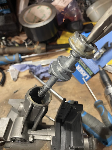
The rest of the ignition barrel mechanism is removed by grinding down the sides of a small boss on the bottom of the ignition housing until it is possible to grip the pin in the middle of the boss with some pliers and pull it out.  The rest of the mechanism can then be easily extracted.

Grind down the boss to expose this pin...

...pull the pin out...

...and pull out the last bit of the ignition barrel.

This still leaves the steering lock mechanism in the barrel.  The easiest way I have found to remove this is to undo the two security bolts holding a plate onto the top of the barrel housing.  I cut a slot in the top of each one using a dremel and used an impact screwdriver to undo them.  This allows the ignition barrel housing to be removed from the steering column and exposes the steering lock mechanism, which can then be levered out and removed.

Two security bolts on top of the ignition barrel housing...

...in the process of removal...

...which then exposes the steering lock mechanism...

...allowing all the components to be removed.

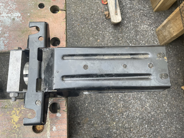
The BMW column mounts need to be modified to fit the AK body.  This involves trimming the top mounting plate of the column and cutting off the left-hand leg of the column mount.  

The top mounting plate needs to be trimmed...

...to leave around 40mm left protruding...

...and the left-hand leg of the column mounting...

...is removed entirely.

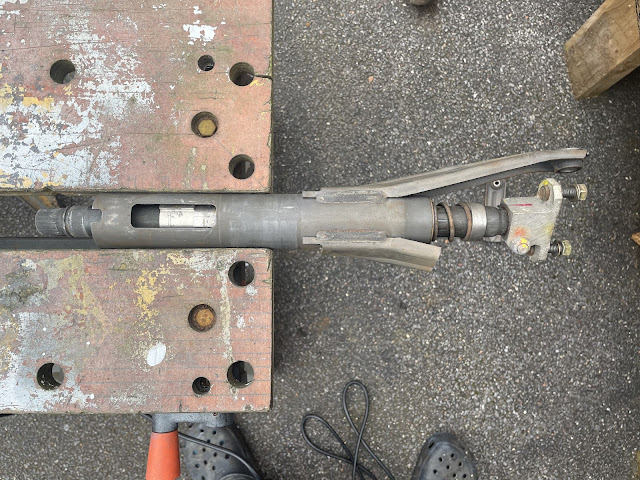
The last "modification" required is to remove the large nut from the end of the lower column section.  From Russ Howell's video series, I know that this nut can clash with the side of the pedal box and that AK had advised the nut is not really needed and can be dispensed with.  Easier said than done, as the nut on my column was stuck fast and no amount of leverage and gentle persuasion could budge it.  I resorted to cutting a slot in the side of the nut with an angle grinder and using a cold chisel to split the nut off the shaft.

The large nut on the lower section of the column...

...needed some minor surgery to aid its removal.

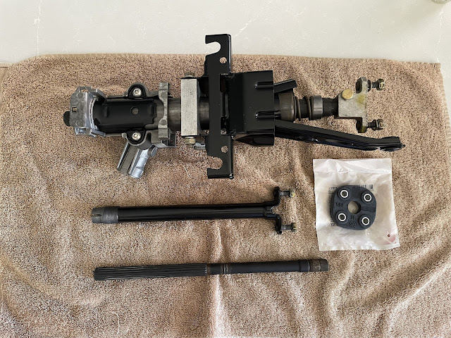
I gave the exposed metal parts of the column a couple of coats of black Smoothrite before reassembly and bought a new rubber steering joint for between the upper and lower column sections.  The column is now ready for installation! 

The modified steering column ready to fit!


Tuesday, 21 May 2024

Steering Part 2 - Power (Steering) Struggles

So my power steering issues still need to be fully resolved...

With my pump issues sorted (See Engine & Gearbox Installation - Part 6) all I needed was to connect up the pump reservoir and hoses and all would be good.

Haha...

Having bought the billet ancillaries bracket from Kyle at LSX Performance I knew that I wouldn't be able to use the standard LS Power Steering reservoir which, as I understand it, slots into the standard Chevy ancillary bracketry.  Kyle did supply me with an alloy tank to suit the kit he had provided, but in the end, I decided there were a couple of issues with it.  

Firstly, the low-pressure spigot on the tank was far too small for the AK-supplied hose and I was worried that I would not be able to get a tight enough seal with a jubilee clip (the AK hose is also braided which restricts the ability of the hose to crush down small enough).

The second issue was that with my shiny header tank and washer tank, the alloy version just didn't really meet my required "bling" standards.

It's good - but not good enough...

This led me to design my own version of the reservoir which utilised some AN-style fittings that would match the size of the low-pressure hose and the inlet port on my power steering pump.

CAD Design for new reservoir...

...using -AN weld-on fittings

I rang around a couple of companies to get a quote for making up my design in polished stainless steel.  I ended up going to XCS Designs, perhaps better known for their own Cobra kits, who are just up the road from me.  Scott, their Workshop Manager, gave me a pretty reasonable quote on the basis that I provided the AN fittings and a weld-on filler neck (which I obtained from that well-known auction site).

My only real issue with that decision was that XCS was going through a particularly busy period (which is good for them) and I had to wait several weeks before my reservoir was ready.  But I think it was well worth the wait!

New shiny reservoir!

Once I had picked up the tank and was ready to install it, I realised that sometimes it pays to just take a little more time planning and thinking things through fully...

The first issue was that on my original tank, the output spigot at the rear was installed right at the bottom of the tank.  In my new design, with the weld-on -10AN fitting, it now sat slightly higher up on the rear of the tank.  This meant that the collar of the AN fitting just clashed with the billet ancillary bracket and prevented the tank from sitting flush against the bracket...

Original tank outlet - at very bottom of the tank...

With weld-on AN fitting, the outlet sits higher on the rear of the tank...

...resulting in the collar of the weld-on fitting clashing with the ancillary bracket

The second issue was that, despite measuring several times, the holes on the new tank did not quite align with the bolt holes on the ancillary bracket.  Comparing the hole positions with the original tank showed them to be quite a way off.  Again, a stark reminder to plan properly and keep checking everything several times and then check again...

The second issue was actually relatively easy to resolve simply by drilling out the mounting holes on the new tank from 10mm to 12mm diameter with a hole drill.  This gave enough wriggle room to get the bolts through the mounting tabs and into the holes on the ancillary bracket.  The added bonus was that by allowing the position of the tank to shift slightly, also solved the first issue above, and the tank now could sit flush against the ancillary bracket.

However, the third issue then identified itself.  I bought a 90-degree -10AN fitting to attach to the rear of the tank and then connect to the -10AN fitting on the inlet of the power steering pump.  However I had failed to consider the dimensions of the -10AN fitting on the back of the tank, and with this installed, there was insufficient space between the front and rear of the ancillary bracket to allow the tank to sit flush as intended.

AN fitting hard against the bracket preventing the tank from sitting flush

This was not a major deal (although it was annoying) as I was able to turn up a couple of 12mm thick spacers from some 20mm diameter aluminium bar with a 10mm diameter hole drilled through the middle.  I also had to buy a couple of slightly longer 10mm diameter bolts to account for the additional thickness of the spacers.

Finally, I could get the tank mounted and the -10AN fitting and braided line routed down towards the pump inlet fitting.

Spacers provide clearance for the rear -10AN fitting

Tank in place and in need of a polish!

I used a 150 degree -10AN fitting to connect the hose to the steering pump inlet.  I originally bought a 180-degree fitting, but the -10 braided hose is not very flexible and I couldn't get the hose to align with the fitting.

150 degree -10AN fitting to align with hose orientation

I needed to angle the hose ends to align with the fitting orientations

Bottom fitting installed

The final fitting of the hose was a bit of a wrestling match.  The short -10 hose had zero flexibility and the only way I could get both ends onto the fittings was to take the reservoir off again, fit the hose to the reservoir and then try and connect the bottom fitting.  Once the hose was secured at both ends, I needed three hands to try and wiggle the reservoir back into place and get the fixing bolts and spacers installed.  It was a great relief when everything was finally in place and all bolts and fittings tightened!

The final connection to the reservoir was the low-pressure line return line from the steering rack.  This is another braided line supplied by AK.  It is installed to the steering rack with a banjo fitting and then routed up to the reservoir.  I used a 60-degree -8AN fitting to connect the hose to the reservoir.

Low-pressure return line from Steering Rack completed

Now all I need to do is get a new high-pressure hose made up with a -6AN fitting on the pump end and this job will finally be done!!!

Tuesday, 30 May 2023

Engine & Gearbox Installation - Part 6 - Ancillaries

With the engine in the car, the last job to complete the installation was to attach the alternator and the power steering pump and fit the serpentine drive belt.

When I bought the engine, Kyle supplied a nice billet aluminium bracket set-up, which once I worked out which holes on the engine it was all supposed to bolt up to, went on quite easily.  There is a smaller bracket which supports the rear of the alternator which sits directly against the cylinder head, the larger front bracket is then set off from the engine block with a number of spacers.

Initial Fit of Ancillary Bracket

Somewhat oddly, despite it being listed as a part of the bracket kit, I didn't seem to have the lower idler pulley with my kit; it was all blister packed and there didn't seem to be a "missing" spot for it.  That created a short delay in proceedings as I had to order a new idler pulley from Summit Racing in the States (I did this to be sure I got the right one, which needed to be for a Z06 Corvette).  Once it arrived it just needed to be fitted with the 110mm M10 bolt supplied with the bracket kit through the pulley and a couple of spacers and screwed into a hole in the engine block.

"Replacement" Lower Idler Pulley

The alternator could then be fitted into place between the front and rear parts of the bracket and held in place with two M10x80 bolts.

The alternator is fixed in place

Then it was 'just' a matter of fixing the Power Steering Pump in place with the three M8x25 bolts supplied.  And with that, a five-minute job turned into a several weeks job...

The first problem was that the Power Steering pump that I had been supplied with the engine, which was a standard GM / AC Delco unit, did not have threaded mounting holes.  The fixings were meant to be much longer bolts that passed through the whole unit and were secured with nuts at the rear.  OK, so I could have bought some longer bolts, but the pump unit is a snug fit between the front and rear parts of the ancillary bracket which would have made it impossible to get any nuts on the bolts in any case.

Another AK builder, who had also got his engine from Kyle, and with who I had been in contact previously, had purchased a new pump from Summit and he had previously given me the details of this.  Figuring he might have encountered the same problems that I was having, I blindly went and ordered the same pump; a performance pump with AN fittings from Tuff Stuff.  This was a long-lead item from Summit and I had to wait several weeks for it to arrive.  Once it arrived, I was relieved to find out that it did have threaded mounting holes and managed to fix it in place on the bracket.

Tuff Stuff 6170ALB-2 Power Steering Pump...

...installed in place

At this point, I noticed my next problem.  The pump that I ordered has the outlet port on the bottom.  This is the high-pressure line and while I knew that I would need to get a new hose made up with an AN fitting to suit, it was pretty obvious that there was going to be insufficient room between the port and the bracket to accommodate an AN fitting and sufficient clearance to form a 90-degree bend (similar to the brake pipe in the picture above, you can not form a bend immediately behind the fittings; there will need to a certain straight length needed to allow the pipe bender to do its thing...).  This was confirmed in my discussions with Adam at Earls, who I had contacted to request a quote for a new high-pressure pipe.

I had two solutions.  Grind away part of the bracket to give clearance for the fitting or find another pump.  I went with the latter option but this time did a bit more research before pressing the order button. I thought a pump was a pump, but reading through the Tuff Stuff catalogue online, there are loads of configurations.  So this time I bought a pump with a top outlet and with threaded mounting holes and with AN fittings.  Summit was showing out of stock so I ordered via Ebay.com but that still took another 8 weeks to arrive!

Does what it says on the box...

...only this one has a top-facing outlet port!

The power steering pulley needs to be installed onto the pump using a special tool.  It's a press-fit but should not be attempted using a hydraulic press as that could damage the pump.  I bought a cheap tool from Amazon; this is basically a threaded bolt that screws into a thread at the end of the pump drive shaft with a nut/flange arrangement threaded onto the bolt.  The flange sits on the face of the pulley and then by holding the main bolt with one spanner and winding the nut down with another spanner, this presses the pulley onto the shaft.  The pulley is installed until the end of the shaft is flush with the front face of the pulley.

It's probably obvious, but the pulley needs to be installed with the grooved flange to the front; this is to allow a puller to grip onto the pulley in the event that it needs to be removed.  If you install it the wrong way around, you will need to take it to your local helpful mechanic to get it removed while he laughs at you; ask me how I know this...

Holley Power Steering Pulley - note which way round it goes...

Pressing the pulley into place...

...until the face end of the shaft is flush with the front of the pulley

I could then install the pump back onto the ancillary bracket; it needed a bit of wriggling to get the pump with the pulley into place with the tubular bracing of the AK Gen III chassis.  I could then get the bolts into place and tighten them to 15ft-lbs / 20Nm.

Finally, the pump is in place!

(Actually, I did have to take the pump out again as I had forgotten to torque up the bracket mounting bolt that is cunningly obscured by the pulley once the pump is in place.  I torqued all the bracket bolts to 25ft-lbs / 34Nm.)

Finally, I could get the serpentine belt looped onto the alternator, power steering pump, water pump, idler and crank, and using a spanner to pull the belt tensioner forward, slipped the belt fully into place and released the tensioner.

The serpentine belt looped into place...

...and over belt tensioner.

With all the faffing around with power steering pumps, that little job only took the best part of five months!!!