Showing posts with label Differential. Show all posts

Sunday 10 March 2024

Couple of Minor Jobs - Part 2

I have finished off a load of small jobs that are not really worthy of a post all of their own.

The first was to add an earth strap between the engine and the chassis.  Just to be on the safe side I bought a 50mm2 earth cable (which should cope with 345 Amps), with a 10mm lug on each end from PCS Cables.  This was bolted into a convenient hole in the engine block at the nearside front.  I drilled and tapped a hole in the top of the chassis rail and ground off a bit of the powder coat to ensure a good contact.

Engine Earth Strap 

I also put the final hose finisher on the crankcase breather hose.  The hose finisher that I originally bought is still hiding in the garage somewhere, probably hanging out with a 10mm socket, and laughing at me.

Breather hoses completed!

I have given the front of the radiator a couple of coats of Eastwood Radiator paint in satin black.  The bare aluminium finish was not quite in keeping with the "stealth" look that I have in mind for the finished car.  I should have done this before I installed the radiator onto the chassis, but I managed to mask up most of the front with newspaper and a couple of old blankets to protect everything from any over-spray.

Radiator masked up prior to painting...

...and after painting and masking removed

I have also added oil to the rear differential and the gearbox as it is far easier to do this while access is good rather than leaving (or forgetting) until the body is on.

I bought 2 litres of Castrol Transmax oil which is specially formulated for limited slip differentials and used a funnel and a length of clear PVC tube to fill the differential with oil.  I managed to get almost all of the 2 litres into the differential before the oil started leaking back out of the filler oil.

Differential oil

Funnel and PVC pipe filling arrangement

For the gearbox, I bought 3 litres of Motul Dexron III oil which is the recommended fluid for the Tremec T56 transmission.  I used the same funnel/pipe setup to fill the transmission and again managed to get almost all of the 3 litres in before the oil started weeping out of the filler hole.

Transmission fluid

Filler hole for T56 transmission

I also have finally got around to welding up the various threaded bungs I have added to the chassis for the fuel tank, gearbox and exhaust mounts.  I treated myself to a day welding lesson at The Machine Shop to try and get the hang of TIG welding. I'm still not "stacking dimes" but at least I managed to master the art of getting a bit more heat and penetration into the welds.  As the body will sit on most of the locations of these bungs, I ground them down flush to the chassis rails and then treated them to a couple of coats of POR15 rust preventative paint.

Powdercoat ground off around area to be welded

A dodgy stack of dimes...

...after grinding welds down...

...and after two coats of POR15


Saturday 24 September 2022

Couple of Minor Jobs - Part 1

 I had a few minor things that I needed to go back and sort out before I totally forgot them and it was too late!

The first was to set the front camber.  

I omitted to do this when I initially assembled the front suspension as a) ideally the front discs need to be installed as it gives a surface against which to measure the camber angle and b) because I didn't read the manual properly and didn't notice that it was something I needed to do!!  (setting front camber is only applicable to the AK Gen 3 chassis).

Unfortunately, the operation required some disassembly of the front suspension; namely the removal of the front shock absorbers so that the top wishbones could be set horizontal.  I also had to remove the front brake callipers to make access to the shock absorber mounting bolts and the upper ball joint mounting bolts slightly easier.

Once the top wishbones were set horizontal I placed a digital level vertically on the front face of the brake disc (handily my level is magnetic so it held itself in place!).  I then loosened the upper ball joint mounting bolts and then gently tapped the top of the axle upright so that I got an angle reading on my digital level of between 0.5 and 0.75 degrees negative camber (i.e. slightly inwards at the top).

I managed to get about 0.65/0.70 degrees on both sides.  I couldn't seem to get the angle to be any much less as the balljoint mounting bolts were at the extreme extent of the slots in the wishbones.  However, the readings were within the AK specified range so all was good.

0.65 degrees of negative camber achieved!

I could then retorque the balljoint mounting bolts and reinstall shock absorbers and retorque the mounting bolts (I needed to use new nuts for the shock absorber mounting bolts as the nylon inserts on the original one looked a bit chewed up upon removal).  Finally, the brake callipers could be reinstalled and I was right back to where I started around 90 minutes previously!!

As the front suspension is now officially completed, I rounded things off by installing the dust caps onto the front hubs.  As with many parts on this project that will never be seen, I had powder-coated them in my favourite shade of metallic red.  I put a slight smear of copper grease around the edge of this to facilitate future removal, should it be required, and then tapped the caps into place with a soft-faced mallet.

Nice shiny dust cap!

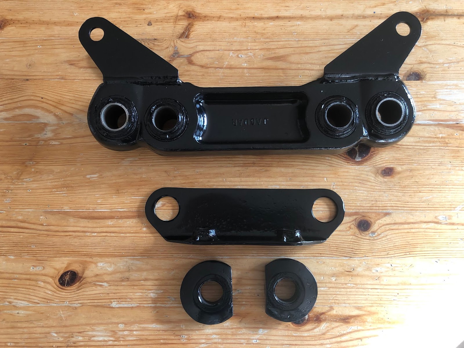
The second job was to replace the differential nose nuts.  These were M10x1.25 Nyloc nuts but when I had installed these and eventually torqued them to the correct specification, I was not happy with the extent of the studs protruding from the nuts.  They only just engaged with the nylon insert in the nuts and I was concerned that this was insufficient engagement to prevent the nuts from working loose during service.

Minimal engagement of stud within Nylon insert in nuts

My plan to overcome this concern was to safety-wire lock the nuts to prevent any possible loosening under vibration.  I had tried drilling the original Nyloc nuts to allow safety lock wire to pass through them.  I bought a jig which was supposed to hold the nuts and then facilitate the drilling of a 2mm diameter hole through two facets of the nuts.  This was next to useless, there was too much play in the assembly and in most cases, I just ended up drilling a slot across the corner of the nuts.

I managed to find some nuts which were pre-drilled for safety wire from RaceTi online.  These had the added advantage of being made from titanium so provided added lightness to the build!  

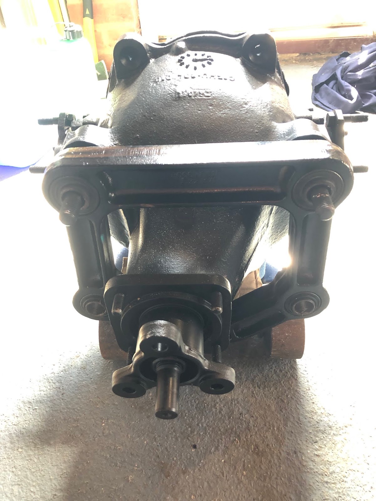
It was a fairly quick task to remove the old Nyloc nuts, replace them with the much lighter titanium items and then torque to the correct specification.  I then wire-locked these nuts in two pairs to prevent them from loosening using stainless steel safety lock wire.

M10x1.25 Titanium Nut - drilled for lockwire.  Photo courtesy of RaceTi

Typical Locking Arrangement for pair of bolts/nuts

The first pair of nuts safety wired...

...followed by the second pair. Job done!

With those items crossed off the list, I could get back onto the main build jobs!


Sunday 7 August 2022

Differential - Part 5 - We need to torque!

 There were a couple of small jobs that I needed to do to complete the installation of the rear differential.

The first was to cut down the 7/16UNF bolts securing the tie bars to the differential and the chassis.  The threaded length of these bolts is much greater than actually required and the protruding length looks a bit odd (to me anyway).

The second was to actually torque up all the various differential mounting bolts.  I didn't do this at the time of the original installation as, quite simply, I couldn't find the details for the necessary torque settings.

An offensive amount of bolt sticky-outedness...

I reckoned about 10mm off the end of the tie bar bolts should suffice.  Before cutting I wound a 7/16UNF die onto the bolt a) so that I could make sure the threads were intact after cutting and b) it made a handy brace to help support the bolts in the vice while cutting!

Die used to help keep bolt in place while cutting

I cut down the bolts with a hacksaw and then reinstalled them into the tie bar mounts, with a further liberal application of copper grease, adding a 7/16 washer on each end and 7/16UNF Nyloc nuts.  The final result was far more pleasing to my eye!

Much better - no unnecessary protrusion!

Now to finish tighten up all the differential mounting bolts.  You would have thought it would have been a relatively simple task to find all the necessary torque specifications, but oddly enough it took me a fair bit of searching before I was sure I had the right values.  This is complicated slightly by the fact that the AK mounting arrangement for the differential is of course not quite the same as the original Jaguar arrangement but my research was also hampered by the various Jaguar service manuals not calling any of the parts/bolt descriptions by anything remotely helpful!

I finally stumbled across a version of the Jaguar XJ40 Workshop Manual on the Jaguar UK forum.  This has a very handy series of diagrams at the front which show the various assemblies throughout the car and the necessary torque settings.  I almost missed this as I initially scrolled straight to the Final Drive Chapter (where of course everything was not called what I expected it to be).  Fortunately, I spotted this section as I was trying to refind the index!

The necessary specifications are as follows:


I was then able to finally tighten all the differential mounting bolts to the required specification and mark them as tightened with my favourite shade of blue nail varnish.

All torqued up and ready to go!


Sunday 8 March 2020

Differential - Part 4 - A strange sense of deja-vu...

In Part 3 of the rear axle assembly I had got as far as installing the rear wishbone tie and the differential tie bars.  I then undid most of that work and, at the back end of last summer, I stripped and re-powder-coated the wishbone tie.  So, one of the first jobs back in the garage for 2020 was to actually reinstall the wishbone tie.  The assembly was cunningly straightforward - almost as if I had done it before...!


Generous reapplication of copper grease on rear diff shafts...

Mounting Bracket re-installed...


Inboard Compliance Buffers back in place...


Wishbone tie re-installed and generously filled with copper grease...


Outboard Compliance Buffers also generously coated in copper grease...

With the outboard compliance buffers installed but not fully tightened I was able to jiggle (technical term) the ends of the differential tie bars into the wishbone tie and tap the bolts into place.


Ends of Diff Tie Bars lubricated with - you guessed it - copper grease...!

Reassembly complete!

The sense of satisfaction at getting this back together was slightly overshadowed by the realisation that I am now back to the same stage that I was last July!   But still, at least I have now done something useful on the car in 2020, so its progress of sorts.

I am still not happy with the length of the thread of the 7/16" bolts that hold the differential tie bars in place.  However, despite many hours of internet searching, it would seem that all UNC partially threaded bolts come with a standard length of the threaded portion (at 1.125 inches).  The only choice I seem to have to make these more aesthetically pleasing is going to be to cut the end of the threaded portion down a bit. 

Another job for the future...


An offensive length of protruding thread...

Friday 2 August 2019

Differential - Part 3 - I'm a bit tied up at the moment

With the differential fitted and the problems with fitting the wishbone tie resolved, I decided to deviate slightly from the AK build manual instructions.

Rather than press on with installing the rear wishbones and hubs (well my hubs aren't ready in any case), I decided to install the rear differential tie bars.  I had seen from Richard's blog post that he had had some fun and games getting these fitted and I figured it would be easier without all the extra weight of the drivetrain if things needed to be jiggled about!

The AK-supplied tie bars are fixed between two chassis lugs and the upstand flanges on the wishbone tie; one on each side of the chassis.

I offered up the tie bars to the chassis lugs but despite trying both ends of both bars, they did not fit between the lugs.  I find this a bit surprising really; as the tie bars are supplied by AK and the lugs on the chassis are welded on by AK, I would expect the fit to be a bit better.  The difference is more than the thickness of the powder coat and would require some metal removal to allow bushings on tie bar end to fit between the lugs.


Nope - that isn't going to fit!

The simple solution used by many others to this issue has been to reach for the file and file down the ends of the tie bar bushing to fit.  But I don't like removing metal unnecessarily so I went for a different approach.

My plan was to ease the chassis lugs apart very slightly to allow the end of the tie bar to fit between them.  This was achieved using a long bolt passed through the chassis lugs with two nuts installed in between the lugs (with washers under the nuts to protect the powder coat).  Using a couple of spanners to tighten one nut and back off the other, this has the effect of spreading the lugs apart very slightly (I did this very carefully as I didn't want to bend the lugs, just ease them apart).


The patented Acme lug-spreader tool...

I am pleased to say that this actually worked!  Using this approach I managed to spread the lugs sufficiently to be able to tap the end of the tie bar in between the lugs - obviously, the presence of the bolt meant that it only just sat between the lugs.  Then it was a case of gently undoing the nuts on the make-shift lug spreader tool, without disturbing the tie bar.  Then the tie-bar could be gently tapped fully into the lugs and centred over the bolt hole.  To make sure these didn't slip out of position while fixing the differential ends I passed one of the AK-supplied 7/16" by 3" fixing bolts through each of the chassis mounts.

Using this approach I had the chassis ends of both tie bars installed in under an hour - result!

The other ends were much easier, in that the ends of both tie bars fitted between the upstand flanges on the wishbone tie - although the holes did not line up perfectly.  This was easily rectified by loosening the mounting bolts of the wishbone tie which gave enough play to allow the bolt holes to line up.  Again I passed a 7/16" by 3" bolt through each of the holes to hold it in place and tightened the wishbone tie bolts back up again.


First tie bar in place....


....both bars in place

After the fun and games I had had with fixing the wishbone tie, it was good to have a job that I was expecting to take some time only take a couple of hours!

I haven't yet tightened up all the nuts and bolts a) because I need to try and work out from the Haynes manual what all the relevant torque settings are, and b) in case I need to loosen any bits off again to facilitate installation of the rear wishbones and hubs.

I will also probably attempt to re-coat the wishbone tie; since I originally thought this was going to be a spare and I used it for my initial attempts at powder coating, there are some areas that are a bit patchy and thin.  Being the perfectionist that I am I want to get a better finish on this piece - it won't be seen (hidden behind the fuel tank) but I want to minimise the chances of any corrosion developing in future.

I will also probably replace the AK-supplied tie bar mounting bolts with some shorter ones; AK provides 3" long bolts which leaves a significant amount of protruding thread.  I reckon a 2 1/2" or even a 2 1/4" long bolt will look neater.

Now I need to crack on with cleaning up the rear hubs...


Monday 8 July 2019

Differential - Part 2 - Being Granted Two Wish(bones)....

With the differential unit in place, next on the list was to install the rear wishbone tie. A simple task from looking at the AK Build Manual.  Well...not quite!

First up was to install the donor mounting bracket, which is simply slid over the main rear differential bolts.


Wishbone tie (top), Mounting Bracket (middle) and Compliance Buffers (bottom)


Mounting bracket installed...

I then applied copper grease liberally to the main rear diff bolts and installed the inner compliance buffers (the ones with the big hole which fits over the main bolts); these are installed with the flat edge towards the outside of the chassis.


Inboard Compliance Buffers installed...

All nice and straightforward so far!

Next on was the wishbone tie; this is installed with the side marked "Jaguar" facing towards the rear of the chassis.

Wishbone tie in place - I see a problem looming...

The outer compliance buffers are then installed again with the flat edge facing outwards.

Hang on!  There's no thread of main rear diff bolts protruding out of the assembly to get the M12 Nylocs onto! WTF!!

Bugger...!

After much head-scratching, drinking of tea, internet research, taking it all apart and reassembling (hoping for a different result), and a teeny bit of swearing, I was none the wiser and I still had no protruding thread onto which to attach a nut...

The problem it seemed was simple; the flange on the back of my compliance buffers seemed to be too thick/big to allow the buffer to sit tightly against the wishbone tie.

This doesn't look right...

Then I remembered something fellow builder Richard had said to me when he was round and I had shown him some of my first attempts at powder coating; which happened to me a couple of the metal compliance buffers.  Richard had said that his buffers/spacers were completely different; they were rubber with a metal insert.

So I had a closer look at the AK Build Manual and the buffers/spacers in the photo in the manual looked completely different from mine.

These are not my spacers! - Photo courtesy of AK Sportscars Ltd

Then I had a lightning bolt moment and I dug out the original wishbone tie that I had received from Simply Performance with my donor axles; remember the one that I had assumed was missing the inner bushes.

Well, guess what - the flange on the back of my metal buffers/spacers seated exactly into the recess in the wishbone tie where the inner bushes should have been fitted.

Fits like a glass slipper!

A quick email to Jon at AK and he confirmed that some of the Jag rear ends did come with a solidly mounted wishbone tie.  So it was a good job I kept the original wishbone tie and even better, I had decided to powder coat it as well! (Although the finish was not as good as the tie that I thought I was using - so I might need to consider recoating it at some point).

Armed with that knowledge, I tried reassembly with the original wishbone tie, and this time it all went together beautifully and I ended up with a goodly amount of thread from the main rear diff bolts sticking out to get the M12 Nylocs and washers onto.

Looking more promising...

Result!

So after several hours attempting a job that should literally have taken five minutes, I need a lie down...or a beer...or both!

Saturday 6 July 2019

Differential - Part 1 - Differential Equations

Having done as much as I can do for the time being on the front end build, it was time to start on the rear end build.

The first task was to press some new bushes into the newly powder-coated pendulum bracket.  The replacement bushes were ordered from SNG Barratt as follows:


More bits courtesy of SNG Barratt

To (hopefully) make the installation a little easier I left the pendulum bracket out in the sun for an hour or two to warm up nicely and put the new bushes in the freezer for a few hours.


Bushes and chips for tea?

I lightly greased the bush housings in the pendulum with copper grease and then pressed the new (cold) bushes into place using my 12T press and a suitably sized impact socket as a drift.  Note that one side of the bush housings on the pendulum has a bevelled edge which helps hold the new bush in position and guides it into the housing when starting to press it in.


Greased bore - note bevelled edge to ease bush insertion...
Pressing bushes into place
All bushes replaced

Next, it was time to unbox the rear differential unit.  The diff is a Salisbury Power Lock (limited-slip) unit with a 3.58 final ratio.  This was fully refurbished by Simply Performance when I purchased the donor axles and has sat in a large box occupying a large space on my garage floor ever since.  The unit is also bloody heavy and I needed some help from Sam to lift it out of the box and onto the cup of my 3T trolley jack.


Shiny refurbished differential unit

The pendulum bracket is then fitted over the nose of the differential with the side marked "Jaguar" facing towards the front of the car.  The upper bushes of the bracket slide onto the shafts at the front of the diff; these had a generous application of copper grease prior to installation.


Pendulum Bracket in place

The rear upper differential bolts are M12 by 70 bolts which are supplied by AK, with M12 washers to sit under the bolt head and 35mm by 14mm washers which are used as spacers between the diff and the chassis.  I assume the 35mm diameter washers are supposed to fit into the recesses on the top of the diff unit but mine did not seem to sit properly and allow the M12 to pass through so I ended up having to flat off the bottom of the washers on the bench grinder.


Rear Diff Bolts and Spacer Washers - Photo courtesy of AK Sportscars Build Manual
"Modified" Spacer Washers

With some careful (skilful?) control of the jack, I managed to raise the differential unit up and slide it forward into position relatively easily (just remember to rotate the input yoke on the diff so that it passes through the aperture in the chassis first).

Then it was just a case of securing all the fasteners (M10x1.25 nuts on the diff nose studs, M16 Nylocs with 1.25" by 5/8" washers on the front diff studs and M12 Nylocs and M12 washers on the rear diff bolts) to hold the diff in place and allow removal of the jack.


Differential installed!

I haven't fully torqued up any of the fasteners at this stage, mainly as I haven't worked out which are the correct settings from the Jaguar XJ40 Haynes Manual yet.  However, from reading Richard's blog and the trouble he had getting the differential tie bar into place, I figured leaving the diff fasteners not fully tightened might allow some play to get the diff tie bars fitted.

Watch this space!