Wednesday 28 September 2022

Brakes - Part 3 - Rear

 The rear calipers supplied AK Big Brake upgrade kit usually are designed to work with 295mm diameter by 10mm thick rear discs (non-vented).  As my donor car came with 305mm diameter by 20mm thick vented discs I was keen to retain this setup.  Fortunately, HiSpec (who make the upgrade kits for AK) were able to adapt the spacer between the two halves of the caliper to accommodate my larger and thicker discs.

As at the front, the new rear calipers are larger than the original donor single-pot items but weigh in at 1.7kg compared to the 2.06kg of the originals.  They also benefit from two pistons per side to improve the application of braking pressure to the pads.

Size comparison - original caliper looks very sad in comparison

2 pistons per side compared to the single piston original

New Ferodo pads (left) are similar in size to the originals

I ordered some new rear discs from EBC brakes.  I went with their USR Sports Series disks which are slotted and come in a black thermic coating to help combat corrosion.

As with the front calipers, the kit comes with new brackets and bolts to fix onto the rear hubs onto which the callipers are attached.  I fitted these and torqued the mounting bolts to 60Nm/44lbf-ft.  

New caliper mounting blocks and bolts - with confirmation that they have been adapted for 305 x 20mm discs

I inserted the brake pads before installing the calipers - again this could be done with the caliper on the car but I figured it would be easier to do it on the bench (or floor as it turned out).  For the rear pads, the kit comes with some springs which need to be slid onto the outer edge of the pads.  I remembered to give the back of the pads a smear of copper grease before inserting them into place.  They are secured by two pins held in place with R-clips, the springs on the pads need to be eased under the pins as they are inserted to hold the pads into place.

Brake pad spring installed on the outer edge of pad...

...and a smear of copper grease added to the rear of pad...

...before pads inserted into caliper and held in place with retaining pins.

The last task before the final installation of the calipers was to adjust the handbrake adjusters on both sides so that the handbrake pads were just rubbing on the inside of the discs (although I think some further adjustment may be required at a later date). I could then bolt the calipers to the mounting blocks and torque the bolts up to 60Nm/44lbf-ft.  

Rear brake discs and calipers done!

And with that, I have probably reached the stage of the build that I was originally hoping to get to at the end of 2019...so only 3 years behind schedule!

Tuesday 27 September 2022

Rear Axle Reassembly - Part 11 - Finally completed

Once my new half shaft spacers had arrived I could get on and (hopefully) complete the rear axle assembly.

Upon removing the spacers from the packaging, I was disappointed to find that they were both made from steel, and not some more exotic metal, as the price I paid for them might have suggested.

Could a golden spacer lie within...No!

I installed both spacers (4mm on offside / 7mm on nearside) and a single rear camber shim on each side initially.  It actually turned out that I needed just the single 4mm spacer on the offside and the 7mm spacer plus two shims on the nearside to get a camber setting of 0.3 degrees negative on both sides.

Spacer in place on differential output flange

Oh look - those shims do fit after all...


0.3 degrees negative on that side...

...and 0.3 degrees negative on the other side.  Job done!

With that done, I could remove all the 7/16" nuts from the half shafts for the last time and replace them with 7/16" Nylocs.  These were torqued up to 90Nm / 66lbf ft.

The next job was to remove the original drive nuts from the hub end of the half shafts and replace them with new items.  The Jaguar service manual recommends that the splined end of the half shaft within the rear hub is covered in thread lock over 30-50% of the radial area.  I used Loctite 270 and covered the rear part of the splined section before reassembly.  As well as a new drive nut I also replaced the conical washer with a new item.  

Today's thread lock is Loctite 270...

...applied over the rear of the splined section

New conical washer and drive nut (note the red insert)

The drive nuts need to be tightened up to a whopping 225lbf ft / 305Nm of torque.  I tightened them up initially using my air spanner.  I then used a large pry bar against the wheel studs and braced against the floor to stop the hub from rotating and dug out the largest of the torque wrenches from my tool arsenal.

Top tip - push the wrench down rather than trying to pull it up or side on otherwise you may end up pulling the chassis off the axle stands.  Also, try and position yourself away from the pry bar.  Mine ended up bending like a banana and if it were to break free from the wheel studs, it will cause serious damage!

Drive nut installed and tightened to ridiculous torque level!

The last step was to install the rear shock absorbers.  These are fitted in place with 7/16" x 4.5" bolts, M12 washers and 7/16" Nylocs in the top mounts and 7/16" x 2.5" bolts, M12 washers and 7/16" Nylocs in the bottom mounts.  AK only appear to supply a single M12 washer per bolt so I splashed out and added an extra washer to have one under the bolt head and one under the nut on all mounts.

Shiney new shock absorber - fitted so adjuster knob is at the bottom and facing inboard.

Mounting bolts - these were given a liberal smear of copper grease before installation

Rear Shock Absorber installed

The final step was to torque down the shock absorber mounting bolts to 38Nm (28 lbf ft) for the upper mounts and 64Nm (47lbf ft) for the lower mounts.  And that is the rear axle finally completed!

Sunday 25 September 2022

Rear Axle Reassembly - Part 10 - Shafts and Shims Shocker

 Finally, I am at the last stage of getting the rear axle/suspension back together and be warned this stage is a right PITA.

The first job on the list was to set the rear camber.  This requires setting the top most point of each of the rear hubs to be 150mm below the top of the rear chassis rail, checking the vertical angle of the face of the rear hubs and adjusting (by inserting shims between the differential output flange and the inboard half shaft flange) until the camber of the rear hub is between 0 and 0.5 degrees negative camber.

There now follows a moment of monumental stupidity which I am amazed I am prepared to admit to on such a globally viewed forum.

There are a couple of options for shimming out the half shafts on a Jaguar rear axle.

  • Spacers of a specific thickness.  Jaguar used spacers of between 3.5 and 7.5mm thickness with Part Number CBC4806xx, where xx is the spacer thickness (e.g. 35 for the 3.5mm spacer).  Although these are only made out of steel, at the price they cost, you would think they were made out of gold!
  • Rear camber shims with Part Number C16621#.  These are 0.020" (approx 0.5mm) thick and cost less than £1 each

I went with the second and cheaper option and ordered 16 shims from SNG Barratt hoping that would be a sufficient number (giving me up to 4mm of shim on each side).

16 Rear Camber Shims for less than £20...

I jacked up the first rear hub until it was 150mm below the top of the chassis rail.  I did this by clamping a spirit level to the top of the chassis rail and setting an adjustable set square on top, with the ruler set to give a depth of 150mm below the bottom of the spirit level.  The hub was then jacked up until it just touched the bottom of the ruler.

Setting height of hub to correct level

I then checked the vertical angle of the hub using a digital spirit level set vertically across the edges of the centre spigot on the hub.  The first reading was 89.25 degrees (i.e 0.75 degrees of negative camber), slightly too high, so some shimming was required.

I found an article on one of the online Jaguar forums that suggested that each 0.5mm shim would adjust the camber angle by around 0.25 degrees. So theoretically I only needed to add one shim.  In reality, I needed to add a few more as, without any shims in place, there is a small flange on the back of the inboard half shaft that bears onto the differential output shaft flange, such that at the point where the bolts pass through there is a gap between the two of around 3.5 to 4mm.  Until that gap is filled, the rear camber shims won't actually have any effect at all.

So I undid the nuts on the inboard half-shaft, which is a bit of a pain as you have to get it in exactly the right spot to get a 7/16" socket in through the U-joints and then you have to turn the differential by hand to line up each nut for removal (and of course repeat the process when you put the nuts back on).

With the half-shaft eased away from the differential flange bolts I could slide on a couple of shims, tighten it all back up and recheck the camber.  Except I couldn't because the hole pattern in my shims did not match the bolt pattern on my differential output flange; two of the holes matched up, but two were way out.

Cue much swearing...

In order not to waste the whole afternoon, I rummaged around in my box of leftover donor parts and found the two original (thick) half shaft spacers.  So I decided to install those just to try and get an idea of what thickness of shimming I was going to need.  After a frustrating and knuckle scraping afternoon of removing and reinstalling the half-shafts on both sides (several times), I had concluded that I was going to need around 4-4.5mm of shims on the offside and 7-7.5mm of shims on the nearside.

Later that afternoon I logged onto the SNG Barratt website to check out spacer options again.  This time I entered the VIN number for my donor vehicle and surprisingly the rear camber shims that I had already bought, did not come up as an option.  The only options were for the fixed-thickness spacers made of gold.  Clearly, I thought, the rear camber shims are for a different year model which has a different bolt pattern.

Annoyingly the spacers were also all on Special Order from SNG.  However, I found them in stock at Jaguar and Landrover Classic Parts.  I decided to order a 4mm and a 7mm spacer and then if necessary I could cut up the rear camber shims in such a way as to make one spacer out of two (or more) if additional thickness was needed.  BTW these two spacers cost over £100...

While I was waiting for the new spacers to arrive, I decided one evening to try and work out the best way to section up my original shims to try and make up a single shim from bits of others.  

It was then that my moment of stupidity hit me right between the eyes...

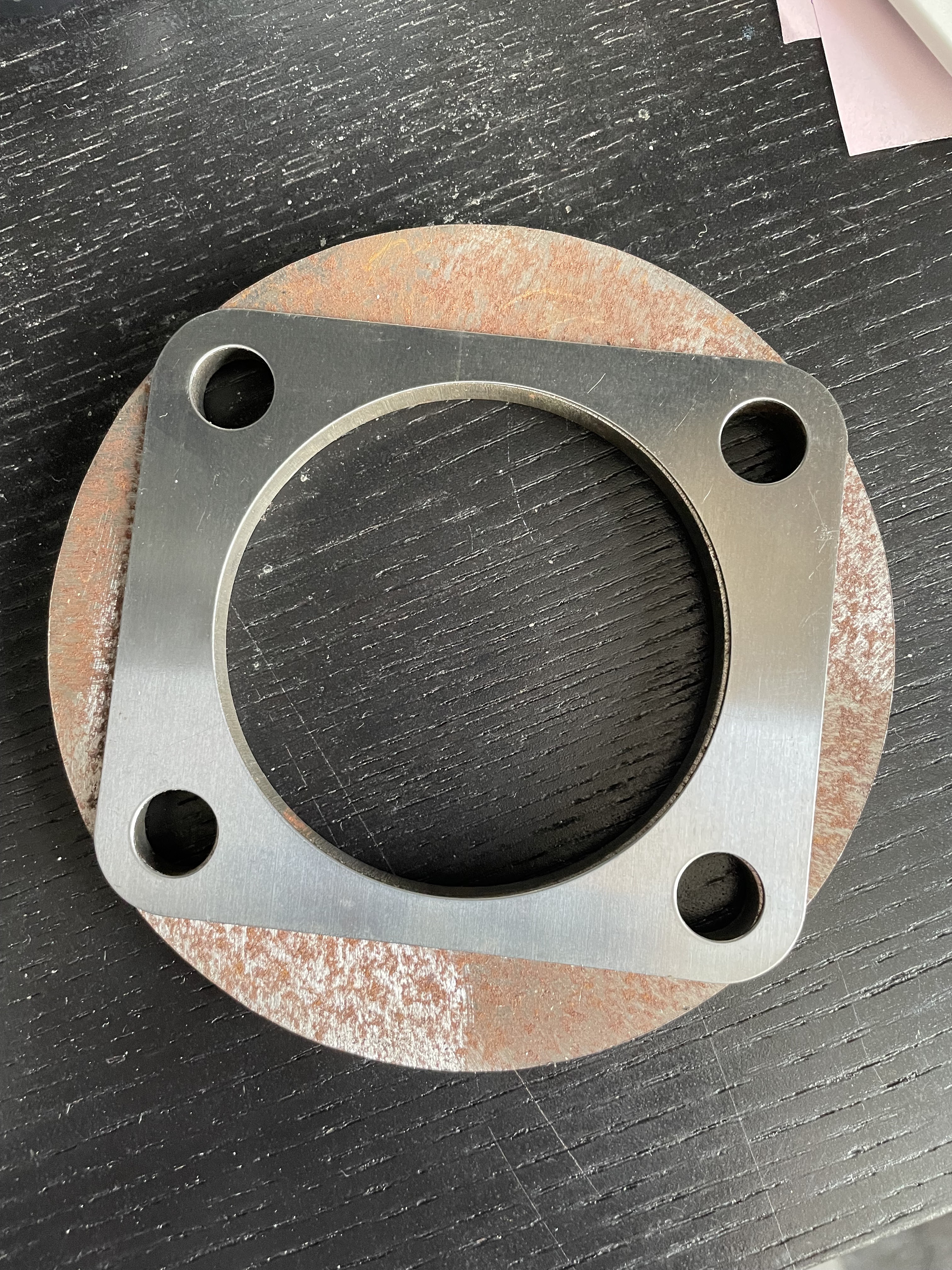
Why would they change the bolt pattern...

...Oh wait - they didn't...Doh!


Still...on the plus side, with needing nearly 12mm in total of shimming, I didn't have enough rear camber shims in any case plus its probably better to have a solid spacer rather than a large number of the thinner shims, particularly on the side needing nearly 8mm of shim (which would be 16 of the rear camber shims).

So maybe it has all worked out for the best!


Saturday 24 September 2022

Couple of Minor Jobs - Part 1

 I had a few minor things that I needed to go back and sort out before I totally forgot them and it was too late!

The first was to set the front camber.  

I omitted to do this when I initially assembled the front suspension as a) ideally the front discs need to be installed as it gives a surface against which to measure the camber angle and b) because I didn't read the manual properly and didn't notice that it was something I needed to do!!  (setting front camber is only applicable to the AK Gen 3 chassis).

Unfortunately, the operation required some disassembly of the front suspension; namely the removal of the front shock absorbers so that the top wishbones could be set horizontal.  I also had to remove the front brake callipers to make access to the shock absorber mounting bolts and the upper ball joint mounting bolts slightly easier.

Once the top wishbones were set horizontal I placed a digital level vertically on the front face of the brake disc (handily my level is magnetic so it held itself in place!).  I then loosened the upper ball joint mounting bolts and then gently tapped the top of the axle upright so that I got an angle reading on my digital level of between 0.5 and 0.75 degrees negative camber (i.e. slightly inwards at the top).

I managed to get about 0.65/0.70 degrees on both sides.  I couldn't seem to get the angle to be any much less as the balljoint mounting bolts were at the extreme extent of the slots in the wishbones.  However, the readings were within the AK specified range so all was good.

0.65 degrees of negative camber achieved!

I could then retorque the balljoint mounting bolts and reinstall shock absorbers and retorque the mounting bolts (I needed to use new nuts for the shock absorber mounting bolts as the nylon inserts on the original one looked a bit chewed up upon removal).  Finally, the brake callipers could be reinstalled and I was right back to where I started around 90 minutes previously!!

As the front suspension is now officially completed, I rounded things off by installing the dust caps onto the front hubs.  As with many parts on this project that will never be seen, I had powder-coated them in my favourite shade of metallic red.  I put a slight smear of copper grease around the edge of this to facilitate future removal, should it be required, and then tapped the caps into place with a soft-faced mallet.

Nice shiny dust cap!

The second job was to replace the differential nose nuts.  These were M10x1.25 Nyloc nuts but when I had installed these and eventually torqued them to the correct specification, I was not happy with the extent of the studs protruding from the nuts.  They only just engaged with the nylon insert in the nuts and I was concerned that this was insufficient engagement to prevent the nuts from working loose during service.

Minimal engagement of stud within Nylon insert in nuts

My plan to overcome this concern was to safety-wire lock the nuts to prevent any possible loosening under vibration.  I had tried drilling the original Nyloc nuts to allow safety lock wire to pass through them.  I bought a jig which was supposed to hold the nuts and then facilitate the drilling of a 2mm diameter hole through two facets of the nuts.  This was next to useless, there was too much play in the assembly and in most cases, I just ended up drilling a slot across the corner of the nuts.

I managed to find some nuts which were pre-drilled for safety wire from RaceTi online.  These had the added advantage of being made from titanium so provided added lightness to the build!  

It was a fairly quick task to remove the old Nyloc nuts, replace them with the much lighter titanium items and then torque to the correct specification.  I then wire-locked these nuts in two pairs to prevent them from loosening using stainless steel safety lock wire.

M10x1.25 Titanium Nut - drilled for lockwire.  Photo courtesy of RaceTi

Typical Locking Arrangement for pair of bolts/nuts

The first pair of nuts safety wired...

...followed by the second pair. Job done!

With those items crossed off the list, I could get back onto the main build jobs!