Saturday 15 August 2020

Rear Axle Reassembly - Part 1

 I have finally got round to starting to put the rear axle components back together.

Part of the delay has been due to my prevarication over whether to powder coat the rear hub carriers, paint them or simply leave them with a bare vapour-blasted finish and give them a coat of something like ACF50 to protect them.

Hub carriers as they came back from vapour blasting....some time ago now...!

ACF50 (Anti Corrosion Formula) is a product developed for the Aerospace Industry and is an anti-corrosion lubricant that bonds to the metal surface and can "creep" into seams, joints, cracks etc to displace moisture and other corrosive fluids.  The manufacturer claims it has the ability to "chemically neutralise road salt'.  Many motorcyclists swear by it to keep their exposed aluminium/metal engine and exhaust parts looking good for longer.  It also displaces water from electrical components.  The downside is that you need to keep applying it (every 6 months or so) to maintain the protection levels and you need to be careful applying it around brake components, so I dismissed that as an option.

That left powder coating or paint.  I preferred the idea of powder coating as it would be more durable and harder wearing.  A single hub carrier would only just fit into my powder coating oven and I even got as far as fabricating a stand/frame to hold the hub in the oven, just clear of the heating elements, before I changed my mind.  The plan had been to powder coat the hubs silver and the silver powder requires a further coating of clear to protect it and stop it from dulling over time.  However, my experiences of getting the second coat of powder to stick evenly to a component, even when 'hot-flocking', have been variable, to say the least.  The hub carriers have a lot of recesses and tricky corners and, being a large component, would heat up in a very uneven way which I was concerned would also affect how the second clear coat would adhere evenly.  So at the 11th hour, I changed my mind and decided to just paint the hubs.

I used a product called Alumablast which is specially formulated for smooth or cast aluminium components, gives a 'fresh cast aluminium' look and has the added benefit of retaining its protective qualities up to 150 degrees C.  

Aluminium Replication Coating - you have to love the US descriptions!

The hub carriers were given a good clean off with a blast of compressed air, a liberal wash down with some Eastwood Pre-Painting Prep and a further blast of compressed air to remove as much of the vapour blasting residue as possible.  Then for good measure, they had a 60-minute session in the oven at 200 degrees to gas out any further impurities before a final wash down with the Pre-Paint Prep and then an application of masking tape around all the bearing seating areas.

I applied several light coats of Aluma Blast to each carrier.  One can is more than enough for both hubs.  The paint actually looks like it has small metal flakes in it when it is sprayed on (not sure if it actually does).  The nozzle did have a rather annoying tendency to clog up, so I had to keep soaking it in thinners between coats.

Bearing Areas masked...

...a couple of light applications...

...looks almost freshly cast!!!

Final painted hub with masking tape removed

So now with both hub carriers painted and looking nice and clean and shiny, the next stage will be to start refitting the bearings and rear hubs proper.


Monday 10 August 2020

Clutch Line

Bending and fitting the clutch line followed much the same process as for the brake lines.  

The clutch pipe is formed from 1/4" diameter copper / nickel pipe.  This was much easier to bend using my pipe bending tool - as it was the correct diameter for the channel in the tool and all the bending marks were for the correct sized pipe. Although bending the pipe by hand, using the pipe bending pliers, took a bit more physical effort than the brake pipes; thankfully I only needed to form one bend with the pliers.

The overall length of the clutch line was around 1.8m so that was a bit of fun to try and handle and get all the bends in the correct plane.  I used the measurements from my CAD model, made the correct allowances for the bend gain (based on 1/4" pipe) as done previously for the brake pipes.  I was pleasantly surprised to get the whole section of pipe bent up correctly the first time!

I must have measured something wrong, however, as the pipe didn't quite reach the bulkhead fitting on my chassis bracket - fortunately, this was an easy fix by simply reversing the bulkhead fitting in the bracket!

I made up another small bracket to hold a further bulkhead fitting on the inner nearside chassis rail (powder coated candy red of course!).  Eventually, there will be a short flexible pipe from this fitting to the clutch slave cylinder that will be mounted on the side of the gearbox.  I worked out roughly where to fit the bracket from looking at Richard Chippendale's rolling chassis on a recent progress visit!

I also made up some additional mounting clips, with just a single hole, to hold the clutch pipe securely along the inside of the chassis rail.

That concludes all the pipes for the front end - next is to tackle the brake pipe run to the rear brakes.

Bracket made up to hold bulkhead clutch fitting

The bracket after powder coating...

...and with bulkhead fitting in place (note I bought some brass locknuts!)

Bracket and fitting in place

Passenger side clutch pipe routing

Driver's side routing

Termination at chassis bracket - one more pipe to go!


Sunday 19 July 2020

Brake Lines Part 4 - Front Brake Lines and Fittings

So with elementary bending and flaring mastered, knocking out the front brake pipes for the Cobra should be a doddle right...?

I started by marking out the positions of the mounting clips and the position of the 3-way brake union on the offside inner chassis rail (all based on my CAD brake pipe routing).

Fixing points for brake clips/unions marked using masking tape

I started with forming the short pipe that runs from the front off-side brake Flexi to the 3-way union.

I realised at this point that my brake-bending tool was completely useless for this pipe as it is impossible to form a bend on the pipe anywhere closer than around 50mm away from the flared end of the pipe; any closer and the brake fittings get in the way and prevent alignment of the pipe within the bending tool.

I resorted to using a couple of offcuts of nylon sheet with a 3/16 hole drilled through them to hold the pipe in the vice and using a piece of 25mm dia steel bar stock cut down with an angle grinder to bend the pipe around.  I checked my bending against a 1:1 drawing of the pipe from my CAD model (sad, I know) and the result was surprisingly close and with the pipe screwed to the Flexi and to the 3-way union the centre of the mounting hole was bang on with my mark on the masking tape.  Result!  Although this turned out to be a bit of beginners luck...

Forming bends close to brake fitting using a 12.5mm radius former

Checking the bending against CAD drawing

Pipe in place...

...and mounting hole aligned perfectly with planned position

Next was the longer pipe run from the 3-way union round to the nearside brake Flexi.  This was a step-up in difficulty level from the previous pipe, being just under 900mm long and needing 8 bends of varying angles (from 30 to 90 degrees).  This is where being able to position the bends exactly where you want them on the length of the pipe becomes important and brings into play those additional marks on the bending tool.

And just to complicate things, when you form a bend in the pipe, it actually stretches along the outer side of the bend, so the pipe actually gets longer - which of course you need to take account of, to be able to position the bends accurately! 

By way of example, the sketch below shows an example length of pipe.  Taking the dimensions between the vertices at each bend (the intersection of the centre line of each leg of the pipe) would suggest that the required length of pipe would be 100 + 100 + 70.71 + 60 = 330.71mm.


However, this would not take account of the pipe stretching when forming the bends so the final pipe would not be the exact dimensions required.

There is some complicated method for working all this out but I stumbled across a table in the owners manual for the extremely expensive Swagelok pipe bender on the internet, which has a handy table of bend gain adjustment factors for pipes from 1/8" (3mm) to 1/2" (12mm).  Basically, this all boils down that for 3/16" pipe, the adjustment factor for a 90-degree bend is 7mm, for a 45-degree bend is 1mm and for a 30-degree bend is basically insignificant.

Measuring out for the above example would then result in the following:
  • P1 would be measured 100mm from the Start of the pipe
  • P2 would be measured 100 - 7 = 93mm from P1 (allowing for the previous 90-degree bend)
  • P3 would be measured 70.71 - 1 = 69.7mm from P2 (allowing for the previous 45-degree bend)
  • The End of the pipe would then be 60 - 1 = 59mm from P3 (allowing for the 45-degree bend as before) 

So actual length of pipe to be cut to achieve the final dimensions in the above sketch would be 100 + 93 + 69.7 + 59 = 321.7mm.

(NOTE -  that this assumes that the pipe is bent from left to right i.e P1, then P2 then P3 - if you were to bend the pipe in the reverse sequence you would actually have different lengths for various sections -  End-P3 (60mm), P3-P2 (69.7mm), P2-P1 (99mm) and P1-Start (93mm) - although the overall length of pipe would be the same at 321.7mm)

So with this exciting theory all worked out, I could take the dimensions of the brake pipe from my CAD model, work out the overall length of pipe needed and mark out the positions of the individual bends making due allowance for the bend gain.

Position of bends marked out

Depending on the required angle of bend, the pipe is positioned in the pipe bender, with the bend position mark aligned with the respective bending mark.  The photo below shows a pipe set up for a 90-degree bend - the start of the pipe is to the left side of the tool, so the position mark is aligned with the 'L' on the rotating arm.  (If the pipe is inserted into the tool with the previous bend or position mark on the right-hand side of the stop edge then the position mark would be aligned with the 'R'.  

Pipe positioned in bending tool - the start of pipe is to the left of the rotating arm so the 'L' mark is used to position the pipe for bending

Perfect 90-degree bend - note I could not perform the first bend using the pipe bender due to the small distance from the pipe fitting

One section of pipe with perfectly positioned bends (except for the last bend close to the pipe fitting on each end)

OK, it wasn't as straightforward as that. 

On the first attempt, I failed to follow BRAKE PIPE TOP TIP 1 and produced a perfectly bent-up length of pipe with a brake fitting missing off one end...

Which brings me to BRAKE PIPE TOP TIP 2.  Make sure before bending any section of pipe that the brake fittings are on the correct side of the bend as they will not pass over the bend once it is formed - again, you may ask me how I know this...

Hmm...something's missing...

I think it took about four attempts to get this pipe right and I wasn't helped by my beginner's luck deserting me when trying to form the tight bends needed at the ends of the pipe adjacent to the fittings.  My subsequent attempts to form these bends using the method I described above resulted in the bends being too large a radius or just in the wrong place which completely cocked up the alignment of the fittings on the pipe with the fittings to which they were supposed to attach to!

In the end, I had to bite the bullet and bought another set of pipe bending pliers from Frost.  These are supposed to form neat bends with a radius of around 15mm with just a twist of the wrist!  Well as usual - not quite.  You can form bends by gripping the pipe with the pliers and giving it a twist, but it does tend to distort the section of pipe ahead of the bend so rather than being straight, the pipe ends up with a distinct curve in it. Also where the pliers grip the pipe, they left a quite deep gouge which didn't look very professional at all.

Eastwood Brake Pipe Pliers - with channels for 3/16" and 1/4" pipe

Form a nice bend and distort the adjacent section of pipe with a flick of the wrist!

My solution was to hold the pipe in the pliers and with both thumbs push the pipe around the bending channel.  Hard work on the thumbs but it gave the desired result.  A bit more geometry was needed as well to work out the actual start point of the bend to know where to grip the pipe with the pliers.

With this section of pipe now bent up to my satisfaction I could check that the positions of for the brake mounting clips were in the correct place and then drill and tap the chassis to allow clips to be fixed in place.  The eagle-eyed will notice that I have powder-coated the backing plates of my brake clips - well I needed to do something to stop them rusting!

Final Brake Mounting Clip

Backplate fixed to chassis with M5 x 8mm Cap-head bolt

Pipe and Clips in place - nearside...

...and offside

The 3-way union was bolted to the chassis using an M7x30 bolt.  The union needed to be spaced off the chassis slightly.  Most people seem to use a number of washers to do this but I made up a small spacer from some 12mm dia stainless steel bar, which I drilled a concentric 7mm dia hole down the middle of, and cut off the required spacer thickness.

12mm dia stainless steel bar stock

Pilot hole drilled down the centre of bar stock...

...before opening up to 7mm dia

3-way union bolted in place with spacer

The final step to complete the front brake lines was to make up the short length of pipe running from the 3-way union to my fabricated bracket.  This turned out to be the most awkward section of pipe to make, although if I wasn't so fussy about how neat it should look, it possibly wouldn't have taken so many attempts...

The main issue was trying to form the two 90-degree bends back to back (with one at 90-degrees to the other) adjacent to the 3-way union.  The first bend needed to be very close to the union, with the second needing to be right at the end of the first bend.  Despite several attempts (more than two but less than fifty...) I couldn't get the two bends to look neat and or get the overall pipe length at both ends.  

The purchase of the second set of pipe bending pliers helped somewhat but in the end, I settled for angling the pipe slightly coming out of the 3-way union and making the second bend a 45-degree angle which made things slightly easier to bend.

Which brings me to BRAKE PIPE TOP TIP 3 - when you have had dozens of attempts to make up a section of pipe and finally create the perfect back to back set of bends, do not rush to make the next bend in the pipe and form the bend in the wrong direction from that required...yes you may ask me how I know...

After a couple of attempts...

...finally managed to bend up final section of pipe!


Pipe route needs to allow for 1/4" clutch pipe to run between pipe and tube stiffener

So that's all the front brake pipes bent up and sorted.  I will blow all the pipes through with a compressed air line before tightening up all the unions.  Now to bend up the clutch pipe to complete all the pipework at the front end.

Engine Update

Back in my January 2020 update post, I dropped some hints about my change in engine choice.  427 cubic inch, titanium rods and, the need for a dry-sump tank...

So if you hadn't already guessed, I am now planning on installing an LS7 engine instead of the LS3.  My engine builder, Kyle, made me an offer I literally couldn't refuse.  He also persuaded me to consider dry-sumping the motor to eek out a few extra horsepowers - hence the need to try and find a location in the confines of the AK for a remote oil tank.

So the revised engine specification looks a bit like this
  • LS7 Pistons - Mahle PowerPak Forged 4032 Alloy for low expansion with Grafal anti-friction skirt coating - modified wrist pins - hot washed and checked
  • Mahle High-Performance Piston Rings
  • Compression Ration approx 11.3:1
  • Competition Cams Camshaft (guaranteed to pass IVA / MOT)
  • Competition Cams reduced travel Hydraulic Lifters
  • Competition Cams Rocker Trunnion Upgrade (with needle roller bearings)
  • LS7 Titanium Conrods
  • ARP High-Performance Big End Bolts
  • Clevite H-Series Big End and Mains Bearings - 
  • MLS Head Gaskets
  • Double Valve Springs
  • Uprated Water Pump
  • New Front Damper
  • LS7 Sump Pan with adaptor for -12 oil lines to remote tank
  • New LS7 Intake with 42 lb per hour Injectors
  • One Piece Manley Pushrods
  • New Gaskets
  • New Sensors
  • New Oil Seals
  • Fly-by-Wire Throttle Body
  • Custom Corvette Front End (Power Steering Pump, Alternator, Idler and Custom Tensioner)
  • Canems ECU and Wiring Loom modified to include immobiliser 
  • Dyno Run and Set-up

Kyle started pulling together all the parts for the engine earlier this year but the Covid-19 pandemic caused a few delays with some of the parts coming from the States so final assembly did not begin until mid-June

LS7 Bare Aluminium Block with pressed in Steel Cylinder Liners

Cam installed and upper main bearings in place - note dowels to assist location of end caps

Forged Steel Crankshaft 2.559in dia Mains / 2.100in dia Rod Journals

Reluctor Wheel (24X) welded to Crankshaft

Pistons and Rods ready for assembly

Piston Ring Gapping

Short Block Assembly complete

Cylinder Heads - CNC Ported / 70cc Chambers - 2.205in dia Titanium Intake Valves & 1.610 in dia S/Steel Sodium Filled Exhaust Valves

Uprated Valvetrain

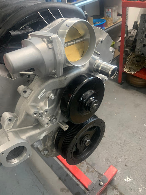
Fly-by-Wire Throttle Body

Sump Adaptor to connect to remote Oil Tank

Assembly almost complete - looking like an engine!

The LS7 was the largest displacement engine in the LS engine series.  It was based on the C5-R engine used in the Le Mans racing Corvettes so is purpose-built for high performance.  It found its way into a number of GM cars between 2006 and 2015 most notably the Corvette Z06.

The stock LS7 produced a respectable 505bhp at 6300rpm and 470lbft torque at 4800rpm.  Kyle built the LS7 for Apple, the AK demonstrator, which put out around 630bhp and a shade under 600lbft torque, some serious gains over stock, and I would have been happy with similar numbers from my engine.

Kyle had the engine hooked up to his dyno at the beginning of July and spent a day checking over for leaks, before a session at fast idle to run in / bed in the engine.  The plan was for Dave from Canems to come and assist with the set-up of the ECU before carrying out the power pulls proper.

On the dyno and ready to rumble...


About mid-day on the day that Kyle was hoping to do the power pulls, I got a phone call.  "Are you sitting down?" he said.  So down I sat, thinking the engine had blown up on the dyno or some other equally catastrophic scenario.  Turned out the numbers on this beast exceeded even Kyle's expectations; 659bhp at 6300rpm and 603lbft at 4900rpm! He was over the moon and so was I!

Dyno output...

...peaking at 658.6bhp and 602.9lbft torque!

Torque exceeds 500lbft from around 3000rpm!


While the engine was still on the dyno I took the opportunity to pop up to Kyle's workshop and check it out in action.  It also gave me the chance to familiarise myself with all the various connections from the ECU to the engine sensors and to get some guidance from Kyle for when I come to start up the engine myself.


The video above of the outside of the dyno room just does not convey the power of this engine - it was like a Force 8 gale blowing out of the exhaust pipes and the whole ground was shaking.  Absolutely awesome piece of kit and I would recommend Kyle without a doubt to anybody wanting to get some serious bang for their buck on the engine front.

I should be picking engine up in a couple of weeks time so I guess I'd better crack on with getting the rolling chassis completed!!