With the engine removed from its stand and hanging from an engine hoist, the next job was to install the flywheel and clutch.
Due to the engine sitting for some time, some light surface rust had appeared on the rear crankshaft flange. I cleaned this up using a Scotch-Brite pad and gave the flywheel mounting flange a good clean with some brake cleaner, including the recess where the pilot bearing will be installed.
The directions for the ARP flywheel fixing bolts that came with my transmission installation kit specified the use of the included ARP lube under the head of the bolts with some Loctite 242 on the threads.
Loctite 242 (or Loctite 'Blue') is a medium-strength thread-locking compound. There is an 'improved' product available, Loctite 243 (obviously), which has an improved oil tolerance and so doesn't require bolts to be scrupulously clean to be effective.
Installation of the flywheel was straightforward; I applied a smear of the ARP lube under the bolt heads and on the top half of the thread plus a drop or two of Loctite 243 on the end of the thread. I held the flywheel up against the crank mounting flange, screwed all the bolts in hand tight and then torqued them up in stages and in an alternating pattern to 85ft-lbs / 115Nm.
(The ARP flywheel bolts have a 12-point head. While I could tighten the bolts up reasonably tight with a normal 14mm socket, when trying to torque them up to the final specification, the 14mm socket did slip on the bolt heads. So rather annoyingly I had to order some 12-point sockets, which meant that I had to remove all the bolts and clean them up while waiting for the new sockets to arrive; had I left them in place, the thread lock would have cured and then when torquing the bolts that would likely have broken the bond rendering the thread locker useless).
 |
| Flywheel installed at 2nd attempt |
I then tapped the pilot bearing into the recess in the crankshaft, using a socket as a suitable drift, until the front face was just flush with the front of the recess. The pilot bearing is a roller-type bearing and was already greased. I didn't add any extra grease to avoid excess lubricant being flung around in the vicinity of the clutch plates.
 |
| Pilot Bearing in place |
I then gave the flywheel a good wipe down with brake cleaner and several paper towels to remove any traces of oil that were on the flywheel from the supplier (and my greasy mitts!) to protect it from rusting. Once I had done that, I did it again, just to be sure!
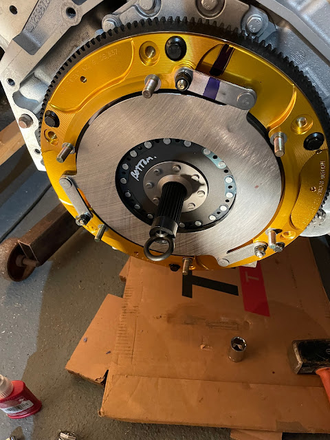
The clutch installation was reasonably straightforward despite my opting for the twin-disc clutch setup. I offered up the first clutch disc to the flywheel using the normal plastic clutch alignment tool that seems to come with all clutches. I then needed to secure the adaptor which holds the floater plate for the twin-disc set up to the flywheel. I put a couple of drops of blue Loctite on the securing bolts and torqued them to 25ft-lbs / 34Nm as per the instructions. At this point, the bottom clutch disc can still spin freely between the flywheel and the floater plate.
 |
| Clutch discs have idiot-proof markings! |
 |
| First (bottom) disc in place |
 |
| Adaptor ring and floater plate installed |

