The normal handbrake set-up on the AK Cobra is a cable-operated system, utilising an XJS handbrake lever in the cockpit, operating a lever mounted above the differential unit that in turn pulls on the handbrake cables connected to each rear hub.
The original AK handbrake set-up, whereby the cable simply pulled directly on the actuator lever, did appear to have a reputation for not being very efficient (based on a read of several internet forums). AK has addressed this and modified the set-up with the cable operating the lever via a pulley set-up to provide twice the pulling power. Improved, but still a bit touch and go come IVA / MOT test time.
 |
| AK Handbrake Modification (from AK Build Manual) |
I decided to make a couple of further modifications to the system myself to improve the handbrake performance.
The first modification involves the XJS handbrake lever. I obtained the lever from Simply Performance at the same time as my donor axles. The photos below show the lever before and after modification...
 |
| XJS Handbrake Lever before initial modification... |
 |
| ...and after modification! |
The second modification involved the purchase of an electronic handbrake kit from Hollin Applications Ltd. This kit was developed for the Motability market in the UK but seems to have gained popularity with many Cobra builders over recent years. The kit includes a linear actuator, an electronic controller and a simple switch. The controller enables the pull / push force on the actuator to be adjusted up to a maximum of 800N or 80kg in old money. It also meets the IVA requirement of preventing the handbrake from being released unless the ignition is switched on (it does also have the problem that the handbrake can't be released if the battery goes flat - but we will cross that bridge later). The switch is a bit basic and will do for initial testing, but it will be replaced with something to match the other interior switchgear (when I decide what that will be...)
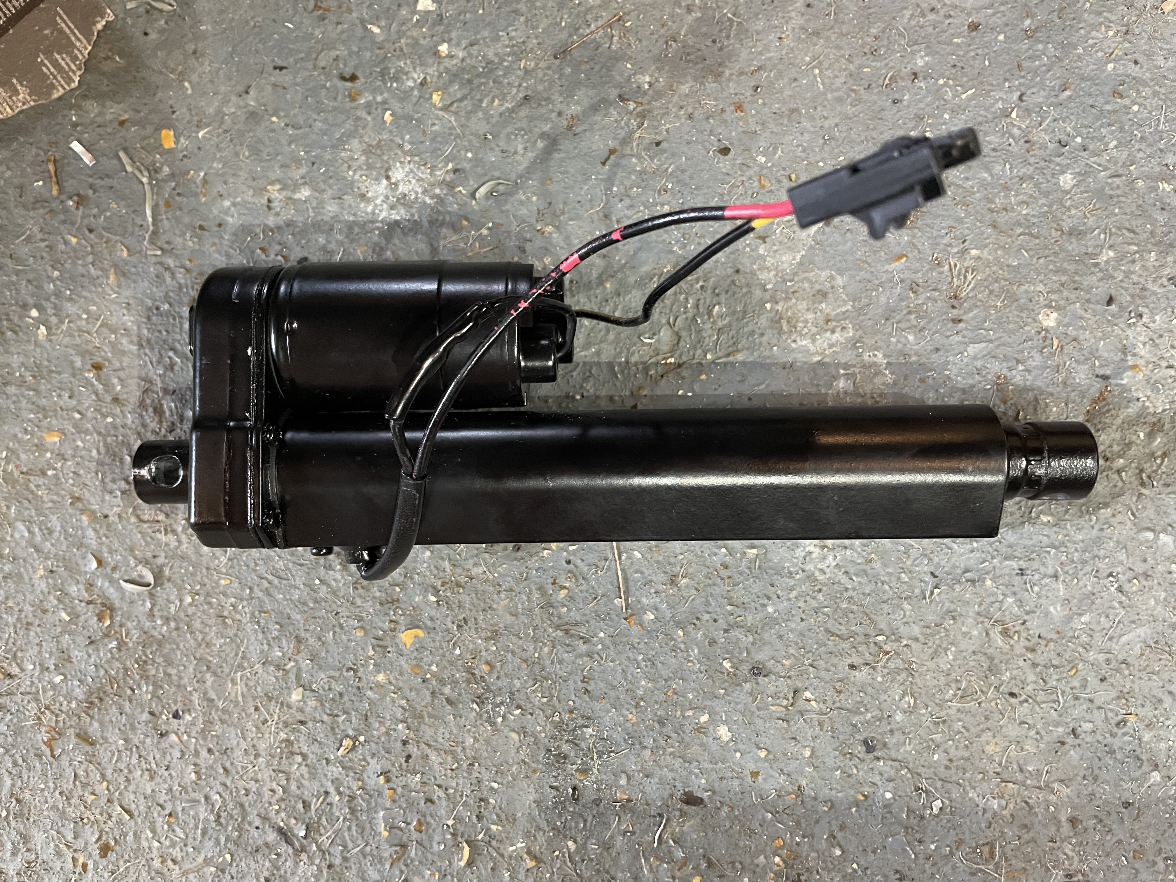 |
| Linear Actuator |
A bracket of some description is needed to mount the actuator to the rear chassis cross-member. Since I made the decision to go with the Hollins kit, AK has actually started using them in their factory builds and has started selling an electronic handbrake kit including a mounting bracket. However, I felt the price they were asking for the bracket alone was a bit steep and as I enjoy spending valuable time that I haven't got, making unnecessary bits for this build, I decided to make my own...
Fortunately, I got a bit of a headstart via Steve Sutton's build blog which referenced a solution by another builder Michael de Kok, who had included the details of the bracket he had fabricated for his own Cobra electronic handbrake install. So, giving credit where it is due, I have borrowed the same design.
I completely forgot to take any photos of the fabrication process, so thankfully you can all just see the final bracket before and after powder coating!
 |
| Final bracket before coating (don't be too harsh on my welding)... |
 |
| ...and after powder coating |
 |
| The actuator is installed into the bracket. |
I then drilled and tapped some holes in the rear cross-member and fixed the bracket/actuator to the cross-member with some M8x1.25 bolts and spring washers.
 |
| The handbrake actuator & bracket are fixed to the rear cross-member. |
I also needed to replace the operating lever from the item that AK supplied. I fabricated a new lever from a 5mm thick steel plate with a small section of steel channel welded on the end. The channel end needed to be reworked with some light grinder action to prevent the lever from fouling on the chassis at full throw.
 |
| New handbrake operating lever |
I trial-assembled all the bits and wired up the control board temporarily to test out the operation. Thankfully it all seemed to work OK with the actuator shutting down at extension once the load from the handbrake cables started coming on; the control box is preset from Hollins at 50kN load.
The final assembly involved powder-coating the operating lever, making up a couple of nylon spacer washers and bolting it all back together with copious amounts of copper grease.
 |
| Final handbrake assembly |