Sunday 30 May 2021

Rear Axle Reassembly Part 3 - Getting Spaced Out...

So with all the bearing races installed into the rear hubs, now I can crack on with greasing the bearings and finally re-building the hubs, yes?

Well not quite.....

While at this point, the AK Build Manual would have you packing the bearings and installing them and the seals back in the hub carriers, the build manual appears to be silent on the subject of checking the pre-load on the bearings.  

Maybe the AK logic (and that it seems of many builders) is that if you have kept all the parts from the donor hubs together as you strip them apart, and make sure you put all the same parts back into the same hubs, then everything will be OK.  

Maybe...although that does presume that everything was actually OK when the hubs were taken apart.  And in any case, the Jaguar X300 Service Manual includes tolerance specifications for rear hub bearing pre-load and requires the preload to be checked when replacing the bearings; so it would seem that this is something that is important to check.

Basically it is necessary to "dry" assemble the hub with the bearings and the largest available adjustable spacer, measure the end float of the hub and use that measurement to calculate the required thickness of adjustable spacer needed to achieve the necessary level of float/pre-load within the required tolerances.

(Note that the largest thickness of adjustable spacer that Jaguar make is 3.47mm.  I purchased a 3.42mm spacer in error but, assuming that my required spacer thickness is less than this, then I should still be able to use it to calculate the required thickness)

The outer bearing is installed on the hub without the oil seal


Hub inserted into carrier and fixed spacer installed (chamfer facing towards inner bearing)


3.42mm Spacer is then installed...


...followed by Inner Bearing (again without oil seal)


ABS Ring placed onto the end of hub shaft and pressed into place


The hub assembly then needs to be put into compression to tighten up the bearings to the spacers.  The Jaguar Service Manual is not exactly clear how to achieve this.  So I installed the stub axle into the hub, installed the original conical spacer and original driveshaft nut and used an air wrench, set to the maximum torque setting, to try and put the whole assembly into a reasonable amount of compression.

Stub axle being installed into hub...

...and then tightened up to put bearings and spacer into compression

The next step is then to measure the end float on the hub.  This needs to be done with a dial gauge.  Fortunately, I acquired such an instrument many years ago when I rebuilt the gearbox on my TransAm; I knew I would find a use for it again one day!

I sat the hub carrier on a spare piece of steel sheet on my workbench to make sure it was sat completely flat and stable.  The magnetic base of the dial gauge was mounted onto my vice and the gauge set onto the face of the hub and zeroed.

I then used a screwdriver between the hub and the carrier to gently lever the hub up as far it would go and checked the reading on the gauge. 

Set-up for measuring end float of hub

Gently levering the hub upwards shows an end float of 0.0135in (0.343mm)


I took an average of several readings, rotating both the hub and the carrier on the bench, ending up with an end float of 0.356mm on the offside hub and 0.324mm on the nearside hub.

From the Jaguar X300 Service Manual the actual required end float should be a minimum of 0.025mm and a maximum of 0.080mm.

So by the power of mathematics it is possible to calculate the mimimum and maximum required thickness of spacer that needs to be installed, in place of the 3.42mm spacer, in order to achieve the correct tolerances.  The spacers come in a range of thicknesses from 2.22mm to 3.47mm, in 0.05mm increments, so it is then a case of selecting the available thickness that falls between the upper and lower tolerance calculated thicknesses.


This then required another order from SNG Barratt, and a short wait for delivery, before I could get on with the final reassembly of the hubs.

(The obvious question that I hear all of you asking is of course "Well could you haved re-use your original spacers?".  And the answer is....no. The thickness of my original spacers was 3.12mm on both sides.  Using these in the reassembly would have resulted in the tolerance being at least 0.1mm (over 100%) out.  So my decision to check this appears to have been the right thing to do.)

Friday 28 May 2021

Gearbox Part 2 - Delivery!

 I ended up ordering a complete installation package for the T56 Magnum transmission from Roadcraft UK.  This included the following items:

  • T56 Magnum Transmission (obviously)
  • McLeod 168 tooth Steel Billet Flywheel
  • Aluminium Bellhousing
  • Roller Spigot / Pilot Bearing
  • Transmission Mount
  • ARP Flywheel mounting bolts
  • All bolts for attachment of bellhousing and transmission

I also opted for the following additional items / upgrades

  • Gearbox yoke
  • McLeod RST Twin Disc Clutch
  • Hydraulic Clutch throwout Bearing

I went for the twin 10.5" disc clutch upgrade since it can handle 800hp with ease and still gives a relatively soft pedal engagement and remains streetable.  The soft pedal element was the key for me.  I still have the nightmare memories of trying to drive my Pontiac TransAm in traffic; the clutch was immensely heavy (although to be fair it was cable operated not hydraulic) and I used to frequently experience the shakes in my left leg trying to ride the clutch in stationary / slow moving traffic.  

After a short delay in delivery (due to the container with all the transmissions going temporarily AWOL) I got a message from Brian confirming my delivery date for end of April 2021.

On delivery day, I received a neatly wrapped pallet containing all the transmission components. 

One shiny new transmission!

Rear Yoke

A well wrapped Bellhousing

Next out of the box were the flywheel and twin-disc clutch.  There's a fair amount of rotating mass with these two components; the flywheel weighs 13.6kg (or 30lbs in old money) and the twin-disc clutch weighs 10.2kg (22.5lbs).  That's a hefty 23.8kg (52.5lbs) in total!

Steel Billet Flywheel

RST Twin-disc Clutch - looks too nice to hide!

Next off the pallet was the hydraulic throw-out bearing.  This is fixed on the end of the transmission over the input shaft and pushes directly on the release 'fingers" on the clutch.  It does away with the normal clutch lever and external slave cylinder arrangement.  This is a standard GM item and comes with the factory style bleed screw arrangement, which requires a special tool to be able to access through the bell housing when everything is bolted together.  First job will be to remove that and replace it with an extended hose and bleeder to make bleeding the clutch a tad easier!

Hydraulic Throw-out Bearing - factory fittings will need to be replaced

And last but not least were the transmission mount, the roller spigot / pilot bearing and a selection of bolts to secure everything together.

Miscellaneous items....and some lube!

Having checked everything out, I put all the components back in their box and put them in the corner of the garage until its time to install the engine.  I need to finish assembling the rear axle first.  Hopefully the presence of a large box of goodies in the corner will give me the motivation to pull my finger out!!!


Rear Axle Reassembly - Part 2 - Bearing down on the matter at hand

With the hub carriers painted, it's time to get on with reassembly the bearings and the rest of the rear hubs.

The first task (already undertaken a couple of months ago) was to dig out the credit card and order a couple of sets of new bearings, seals and a few other parts that didn't survive the strip-down operation and needed to be replaced. 

The shopping list looked a bit like this...


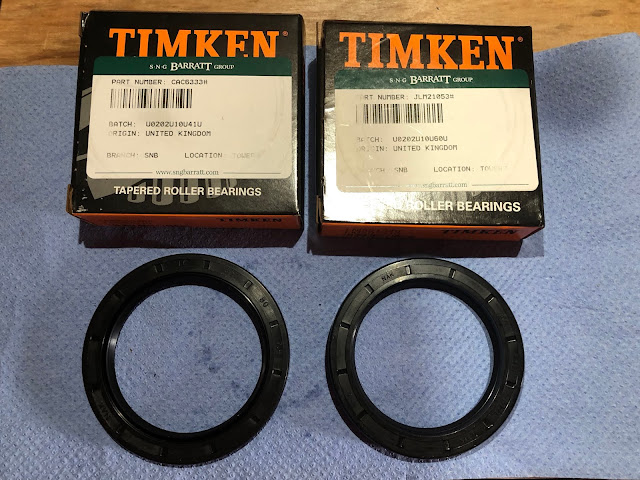
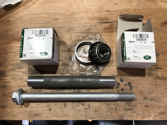
The Bearing Kit includes both the inner and outer bearings plus the two oil seals and works out a fair bit cheaper than buying the parts separately. I decided to buy new outer pivot pins and pivot pin sleeves as these components on one side of my donor hubs were very corroded when I stripped them down.

Bearing Repair Kit

New Pivot Pin, Sleeve and Taper Bearings

Reassembly of the hubs commenced with the installation of the new inner and outer bearing races.  As with the front hubs, I took an angle grinder to the original bearing races to use as drifts for installing the new races.  The new bearing races had a few hours in the freezer and the hub had a gentle warming at 140 degrees C for 30 minutes or so in the oven in order to facilitate the installation process.

Original races fettled gently to use as drifts to install new bearing races

All good in theory....

I read with great amusement Terry's version of events for inserting the rear races in the hubs in his blog.  

"Heat the oven to 150 degrees (fan oven 140) or gas mark 2 and cook for 30 minutes.  Remove from oven an if the races don't just drop in, they will need just a few taps with a bearing drift."

"Just drop in" and "a few taps", for me at least, translated into an average of an hour per race of tapping with a large club hammer, increasing to hitting as hard as possible and the air turning and ever increasing blue with me swearing every time I hit my hand with said club hammer or pinched my fingers between drift and bearing as I applied serious force to said drift with said hammer...!

Four hours, several bruised fingers and blood blisters later and the races were installed and fully seated.


Installing outer bearing race...

Outer bearing race fully seated...

...together with the inner race

Next I installed the fulcrum races into each hub.  Ironically, given how bloody hard  these were to remove, these all did "tap" in relatively easily. That is, relative to the effort to install the main races; the fulcrum races did still require some considerable thumping with a large hammer and a suitable drift to persuade them into place.

Using old bearing race to install new fulcrum races...

...which was "gently tapped" home to fully seat bearing race

With that job done, it felt like some progress is being made again.  Next step will be to install all the bearings and complete rebuilding of the hubs.


Tuesday 25 May 2021

Gearbox Part 1 - Now for a Live Transmission from our on the spot reporter....

For those of you who have been following this blog, you will recall that my original intention was to use an LS3 engine with a Tremec TKO600 gearbox.  The TKO600 is a 5 speed transmission capable of handling up to 600 lb-ft of torque.

So despite my change of plans on the engine front, with my Kyle Rushall-built LS7 chucking out a whopping 603 lb-ft of torque, the TKO600 unit should still have sufficient capacity (let's face it, the tyres will probably lose traction before the gearbox implodes....).  There was just one small problem....

Having left my decision to order the said transmission from Roadcraft UK to late Spring 2020, the ongoing COVID pandemic was resulting in a shortage of deliveries from the US of A.  There were no TKO600s to buy!

Plan A - Tremec TKO600 5-speed Transmission (Photo courtesy of Tremec)

Then in Autumn 2020 Tremec made the decision to stop making the TKO gearboxes, replacing them with its new 5-speed TKX transmission.  This is basically an improved TKO, with improved durability for high RPM shifts, still with a torque capacity of 600 lb-ft, but intended as an aftermarket replacement transmission that can be fitted without significant modification to chassis / floorpans.  Small problem though, still no deliveries from the States and Brian at Roadcraft UK wasn't even sure when deliveries of the new transmission might commence.

Some of the bits that make the TKX improved...but still can't get one! (Photo courtesy of Tremec)

Brian contacted me in March 2021 and said that he had a consignment of Tremec T56 Magnum transmissions on the way and due for arrival shortly.  The Magnum is the top of the line of the Tremec aftermarket transmissions.  It is a 6 speed transmission, capable of handling 700 lb-ft of torque, and is essentially an aftermarket version of the TR6060 transmission which is factory fitted to recent cars such as the Dodge Viper, Dodge Challenger and Chevrolet Camaro.  Its basically bulletproof!

T56 Magnum Transmission (Photo courtesy of Tremec)

My only concern with using the Magnum 'box is that it is slightly longer than then TKO gearboxes, which results in a very short prop shaft and, due to the slight misalignment between the output shaft of the gearbox and the input shaft on the rear differential, ends up with the prop shaft being at a significant angle to the line of the gearbox and differential; I was worried that the angle would put undue pressure on the universal joints, especially given the power output of the engine.  

Resulting prop shaft angle due to short distance between diff and end of T56 transmission (photo courtesy of Mark Clayton's build blog)

However, a quick chat with Jon at AK Sportscars reassured me that they install a large number of Magnum boxes in their factory builds and demo cars and do not see the prop alignment as an issue.

So decision made, a deposit was paid to Brian at Roadcraft UK, and I could put my feet up and wait for my gearbox to arrive!


Saturday 8 May 2021

Update - Project Snake is still alive!!

 So I haven't posted anything on this blog for some time now - the last update was in August 2020.  There is a reason for that.  It's a simple one.  The fact is, I haven't done very much on the car at all!!

The year of 2020 turned out to be a very strange one, as I sure it has been for everyone.  The year of COVID-19, lock-down, working from home, a false dawn followed by another lock-down, a non-family Christmas and finally some hope on the horizon with the development of a vaccine.

I was fortunate enough to be able to continue to work from home.  But despite saving myself typically 3 hours a day by not having to commute into London, I have still not managed to find and use those hours to do anything constructive!  Work seemed to expand to fill my time and blur the boundaries between work life and home life.

I did manage to get a number of projects sorted around the house, which will hopefully get me in my wife's good books and allow me to justify some serious garage time in 2021, but largely for last year, Project Snake was relegated to the bottom of the priority list.

That's not to say I did absolutely nothing.  I did make a start on reassembly of rear hubs and I did a bit of planning and made some firm decisions on brakes and gearbox and have ordered a few parts in ready to crack on.

Hopefully there will be a few more regular updates coming this year and a lot of progress on the build!  Fingers crossed!

First job however is to have a bloody good tidy up of the garage - over the course of the last year the cobra body shell seems to have disappeared under various boxes and general detritus...

There's a Cobra in there somewhere...!!!


Saturday 15 August 2020

Rear Axle Reassembly - Part 1

 I have finally got round to starting to put the rear axle components back together.

Part of the delay has been due to my prevarication over whether to powder coat the rear hub carriers, paint them or simply leave them with a bare vapour-blasted finish and give them a coat of something like ACF50 to protect them.

Hub carriers as they came back from vapour blasting....some time ago now...!

ACF50 (Anti Corrosion Formula) is a product developed for the Aerospace Industry and is an anti-corrosion lubricant that bonds to the metal surface and can "creep" into seams, joints, cracks etc to displace moisture and other corrosive fluids.  The manufacturer claims it has the ability to "chemically neutralise road salt'.  Many motorcyclists swear by it to keep their exposed aluminium/metal engine and exhaust parts looking good for longer.  It also displaces water from electrical components.  The downside is that you need to keep applying it (every 6 months or so) to maintain the protection levels and you need to be careful applying it around brake components, so I dismissed that as an option.

That left powder coating or paint.  I preferred the idea of powder coating as it would be more durable and harder wearing.  A single hub carrier would only just fit into my powder coating oven and I even got as far as fabricating a stand/frame to hold the hub in the oven, just clear of the heating elements, before I changed my mind.  The plan had been to powder coat the hubs silver and the silver powder requires a further coating of clear to protect it and stop it from dulling over time.  However, my experiences of getting the second coat of powder to stick evenly to a component, even when 'hot-flocking', have been variable, to say the least.  The hub carriers have a lot of recesses and tricky corners and, being a large component, would heat up in a very uneven way which I was concerned would also affect how the second clear coat would adhere evenly.  So at the 11th hour, I changed my mind and decided to just paint the hubs.

I used a product called Alumablast which is specially formulated for smooth or cast aluminium components, gives a 'fresh cast aluminium' look and has the added benefit of retaining its protective qualities up to 150 degrees C.  

Aluminium Replication Coating - you have to love the US descriptions!

The hub carriers were given a good clean off with a blast of compressed air, a liberal wash down with some Eastwood Pre-Painting Prep and a further blast of compressed air to remove as much of the vapour blasting residue as possible.  Then for good measure, they had a 60-minute session in the oven at 200 degrees to gas out any further impurities before a final wash down with the Pre-Paint Prep and then an application of masking tape around all the bearing seating areas.

I applied several light coats of Aluma Blast to each carrier.  One can is more than enough for both hubs.  The paint actually looks like it has small metal flakes in it when it is sprayed on (not sure if it actually does).  The nozzle did have a rather annoying tendency to clog up, so I had to keep soaking it in thinners between coats.

Bearing Areas masked...

...a couple of light applications...

...looks almost freshly cast!!!

Final painted hub with masking tape removed

So now with both hub carriers painted and looking nice and clean and shiny, the next stage will be to start refitting the bearings and rear hubs proper.


Monday 10 August 2020

Clutch Line

Bending and fitting the clutch line followed much the same process as for the brake lines.  

The clutch pipe is formed from 1/4" diameter copper / nickel pipe.  This was much easier to bend using my pipe bending tool - as it was the correct diameter for the channel in the tool and all the bending marks were for the correct sized pipe. Although bending the pipe by hand, using the pipe bending pliers, took a bit more physical effort than the brake pipes; thankfully I only needed to form one bend with the pliers.

The overall length of the clutch line was around 1.8m so that was a bit of fun to try and handle and get all the bends in the correct plane.  I used the measurements from my CAD model, made the correct allowances for the bend gain (based on 1/4" pipe) as done previously for the brake pipes.  I was pleasantly surprised to get the whole section of pipe bent up correctly the first time!

I must have measured something wrong, however, as the pipe didn't quite reach the bulkhead fitting on my chassis bracket - fortunately, this was an easy fix by simply reversing the bulkhead fitting in the bracket!

I made up another small bracket to hold a further bulkhead fitting on the inner nearside chassis rail (powder coated candy red of course!).  Eventually, there will be a short flexible pipe from this fitting to the clutch slave cylinder that will be mounted on the side of the gearbox.  I worked out roughly where to fit the bracket from looking at Richard Chippendale's rolling chassis on a recent progress visit!

I also made up some additional mounting clips, with just a single hole, to hold the clutch pipe securely along the inside of the chassis rail.

That concludes all the pipes for the front end - next is to tackle the brake pipe run to the rear brakes.

Bracket made up to hold bulkhead clutch fitting

The bracket after powder coating...

...and with bulkhead fitting in place (note I bought some brass locknuts!)

Bracket and fitting in place

Passenger side clutch pipe routing

Driver's side routing

Termination at chassis bracket - one more pipe to go!