Sunday, 8 March 2020

Differential - Part 4 - A strange sense of deja-vu...

In Part 3 of the rear axle assembly I had got as far as installing the rear wishbone tie and the differential tie bars.  I then undid most of that work and, at the back end of last summer, I stripped and re-powder-coated the wishbone tie.  So, one of the first jobs back in the garage for 2020 was to actually reinstall the wishbone tie.  The assembly was cunningly straightforward - almost as if I had done it before...!


Generous reapplication of copper grease on rear diff shafts...

Mounting Bracket re-installed...


Inboard Compliance Buffers back in place...


Wishbone tie re-installed and generously filled with copper grease...


Outboard Compliance Buffers also generously coated in copper grease...

With the outboard compliance buffers installed but not fully tightened I was able to jiggle (technical term) the ends of the differential tie bars into the wishbone tie and tap the bolts into place.


Ends of Diff Tie Bars lubricated with - you guessed it - copper grease...!

Reassembly complete!

The sense of satisfaction at getting this back together was slightly overshadowed by the realisation that I am now back to the same stage that I was last July!   But still, at least I have now done something useful on the car in 2020, so its progress of sorts.

I am still not happy with the length of the thread of the 7/16" bolts that hold the differential tie bars in place.  However, despite many hours of internet searching, it would seem that all UNC partially threaded bolts come with a standard length of the threaded portion (at 1.125 inches).  The only choice I seem to have to make these more aesthetically pleasing is going to be to cut the end of the threaded portion down a bit. 

Another job for the future...


An offensive length of protruding thread...

Sunday, 16 February 2020

Welding Practice

One of the main issues hampering my progress on Project Snake has been the state of my garage.  Never the tidiest person at the best of times, over the winter the garage has become a bit of a dumping ground.  I spent a couple of days having a very early spring clean which made things look a lot better.  However, I was still fed up of tripping over my welder(s) and gas bottles which always seemed to be in the way no matter where I put them.

Having added a TIG welder to the tool arsenal last year, I had decided that the disposable gas cylinders were a waste of money and invested in two Hobbyweld Plus size gas cylinders; a 5% C02: Argon mix for MIG welding and an Argon only cylinder for TIG welding.  

To tidy up the storage of the various welding paraphernalia and make it all a bit more portable (the MIG welder and gas cylinders are not exactly easy to handle) I decided to knock up a welding cart.  As well as freeing up some space I thought that it would also give me some good practice with the hot metal glue gun.

I produced a design for the cart in CAD and ordered the necessary lengths of steel section and plate.


CAD Design for Welding Cart

The bottom frame was made from 50x25 RHS while the rest of the frame was 25x25 SHS with 2mm Steel Plate for the shelves.  

Some various progress photos are shown below.  I think my MIG welding skills have improved somewhat after undertaking this project.  It is still very frustrating though, to lay down a series of really nice looking welds and think you've cracked this lark, to follow them up with the crappiest blobbiest bit of weld ever seen... Still, practice makes perfect.  Getting the torch angle right seems to be the key to getting a nice looking weld as well as a bit of a gap between the parts to be welded.


Steel for Bottom Tray cut and prepped
Looks nice - but a bit blobby...
Corner after welding and grinding
Bottom Tray complete
Steel for shelves cut and prepped
Shelf frame - various levels of weld quality...
Shelf top welded on
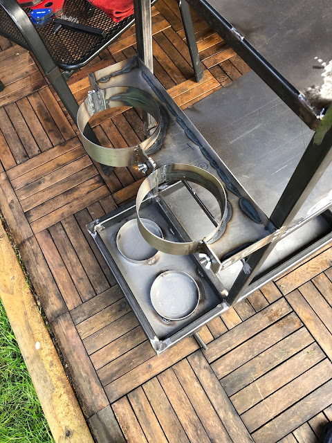
Using a gas cylinder to form Bottle bracket
Bottom bottle supports in place
Starting to take shape
Handle side cut and shaped...
...and end of handle notched to fit.
Upper bottle mount formed from 50x2mm steel strip
Tapping bottom tray for some casters
Heavy-duty casters - good for 200kg each!
Wheels and several coats of Hammerite Smooth

Have to say that I'm quite pleased with the final outcome.  A couple of bits need some fettling; the upper bottle stay doesn't quite tighten up with the bottles in place.  I also rushed the painting a bit, trying to beat Storm Ciara, and forgot to wipe all the grinding dust off the shelves before painting; this led to some vigorous sanding down and another two cans of Hammerite.  The finish is still not great but largely hidden by the welders, so it will do.

Cart loaded up...
...and ready for action

So that's tidied up some corner of the garage - time to get on with the rest of the Cobra build!!

Sunday, 19 January 2020

Project Snake Update - Jan 2020

Happy New Year to everybody!

I have just realised that it is also just over a year ago that my AK body/chassis kit was delivered.  So it seems like a good point to take stock of where I have got to in the build process.

I also recently discovered that my kit delivery date of 11 January (2019) is the same date as Carroll Shelby's birthday (11 January 1923).  An interesting coincidence!

Delivery Day - 11 January 2019

As it currently stands, I have not made as much progress as I would have liked. The front suspension/axles are complete (minus brakes) but at the rear, I have only got as far as installing the differential.  I had hoped to be at rolling chassis stage by this time.

Front axle complete except for brakes

Rear Differential Unit in place

I have got a lot of the parts for the rear axle prepped and ready to install.  My decision to prep a lot of the parts myself (home sandblasting and powder-coating) took a lot longer than I anticipated (but hopefully saved me a bit of money and added to the satisfaction of doing as much as I can myself).

Rear axle components prepped and powder-coated ready for re-assembly

I have also not really had many opportunities to do much on the build since my last post back in October 2019.  Many things contributed to this.  Work went a bit mental back in the autumn and I spent quite a few weekends having to work rather than play!  We also had some work done on the house (which is still not fully finished), having most of the downstairs floors replaced.  This meant clearing out the contents of all the rooms and a lot of this stuff found its way into the garage, with the result that working space and access to anything was severely hampered.

Even when I did find some time (and make some working space) I found myself thwarted by some unforeseen issues.  I bought myself a 3HP compressor with a 100-litre receiver back in the summer; this performed faultlessly during all the sandblasting that I was doing at the time.  

New compressor - doesn't like the cold...

When I came to try and use the compressor in late autumn, it would not start.  There was a brief humming from the starter before it blew either the fuse in the plug or tripped out the garage power supply!  

I was worried that the starter capacitor was faulty. But after the usual extensive internet-based research, it seems that 3HP is right on the limit of what a domestic electricity supply can provide, especially if the plug is at the end of a long run of cable (such as a garage). Also during cold weather, the overall demand can affect the actual voltage supplied.  Additionally, as the temperature drops the viscosity of the oil in the compressor motor increases.  The result of these factors is that, in colder conditions, the compressor motor can not produce enough power to overcome the higher viscosity of the oil and effectively stalls (and blows the fuse).  

This can be overcome by heating the compressor oil (using a strategically applied heat gun) but took a long time (and spare fuses) before I managed to coax the compressor to turn over.  Hence not a practical solution for trying to do some quick jobs...

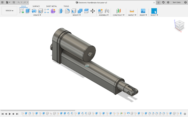
Time has not been wasted though.  I have been doing some planning of the next stages, including the brake and fuel line routing and fixing (no ordinary P-clips will be used in this build!) and I am also toying with the idea of utilising an electronic handbrake based on a 12V linear actuator.

Starting to mock-up handbrake set-up in CAD

The next list of jobs to do are:

  • Extract broken screws from one of the rear hubs;
  • Clean and powder-coat ABS rings from rear hubs (these hold the rear axle stub in place);
  • Reassemble rear hubs;
  • Install new universal joints in driveshafts;
  • Install hubs/driveshafts and rear wishbones;
  • Install rear shocks;
  • Cut down rear brake backing plates and powder-coat;
  • Install handbrake shoes and springs in hubs.

The other main development in the progress of Project Snake has been the engine.  My original plan was for a Chevy 6.2L LS3 motor.  This was going to be built by Kyle Rushall.  Kyle and I have been exchanging texts over the past few months about the exact specification of the motor I was after.  In the end, he offered me an alternative engine at a price that I couldn't really refuse.

I'm going to leave you all hanging for the moment as to the final spec, but it will be a 427 cubic inch engine (but not a Ford...), it has titanium con-rods and I need to find somewhere in the confines of the AK body/chassis to locate a dry-sump tank...

A titanium rod - 464 grams compared to over 600 grams for a steel rod

Kyle has started prepping the block and heads.  The engine build should commence around the end of January and is due for completion sometime in March 2020.

The downside is that the new engine is a "bit" more expensive than I had previously budgeted for so I need to rethink spending plans for the next stages while I save up!


Tuesday, 3 September 2019

Strippers and Dubious Chemicals

My last few blog posts have dealt with a few "issues" that I have encountered, the outcome of which is that I need to redo the powder coating on a number of parts.

One of the main reasons for powder coating the parts in the first place is that the coating is very durable.  In other words, it's a bugger to remove.  I had a couple of attempts with the sandblaster and various sanding discs and wire wheels; these would eventually remove the majority of the coating but would take a heck of a long time. 

If I lived in the US there would appear to be a number of chemical products available to strip powder coat.  However, none of them are available in the UK.

The internet suggested that, after giving the surface a good abrading to remove the top surface of the coating, paint stripper could be used to remove the remaining powder coat.  Well, normal Nitromors paint stripper had zero effect.

Further research suggested that to be effective, the paint stripper needed to contain a particular chemical ingredient, namely Dichloromethane (DCM).  This was a common solvent many years ago and used to be widely used in paint strippers.  But, probably for good reason, in the modern health and safety-conscious era, it is has been removed from most products.

It took some tracking down but I did manage to find some industrial strength paint stripper containing DCM on the well-known internet auction site and purchased 5 litres.

Innocuous packaging, limited H&S warnings (and no data sheet supplied with the product...)

I need to recoat the rear wishbone spacer tubes and the rear wishbone tie.  I gave these parts a quick session with the angle grinder/flappy wheel combo (and in the case of the wishbone tie, some wire brush treatment to get into the recesses) to scratch up the surface of the powder coat finish.  These were them brushed liberally with the professional strength paint stripper and left to soak for a few minutes.

Health and Safety Tip - DCM paint stripper is potent stuff.  Even outside in well-ventilated conditions, I could smell the solvent content!  Make sure you wear gloves, long sleeves and eye protection.  I got some small splashes on my skin when brushing the stripper on and it starts to burn any exposed skin immediately.  Also, work quickly; this stuff burns even through gloves!  After just a couple of minutes of holding the parts while applying the stripper my fingers were starting to tingle!

The potency does mean that the product is extremely effective.  It only took a few minutes for the surface of the abraded powder coat to start wrinkling and using a wire brush I was able to remove the majority of the original coating.

Less than 5 minutes for paint stripper to do its stuff...

After a wire brushing and rinse off with water

Wishbone tie after flappy wheel/ wire brush treatment

After a few minutes of soaking in paint stripper...

...the majority of old coating could be removed with a wire brush

After rinsing and drying

These parts were then re-prepped for powder coating.  I gave the spacer tubes a thorough going over with the grinder and sanding discs to try and remove as much of the surface pitting as I could.  These and the wishbone tie then had another session in the sandblasting tent before an application of Afterblast.

Wishbone tie after sandblasting...

...and after etching with Afterblast

The wishbone tie was then recoated in Satin Black; this time around I made sure to get a good coating of powder all over the part prior to curing.

Ready for coating (again...)

After curing - better than the first time!

For the wishbone spacer tubes, I tried another approach for the application of the candy red topcoat (another technique sourced from internet research...).  The High Chrome coat was applied and cured as before. This time though, rather than allowing the parts to cool and reheat them prior to applying the candy coat, I tried a technique called 'hot flocking'.  This technique involved applying the second coat to the parts as soon as they were removed from the oven after curing the first coat.  Due to the parts being at or just below curing temperature, the second coat of the powder started to cure as soon as it is applied to the part.  This also meant that the powder adhered far more readily to the part and did not get blown off as easily.  The parts were then cured in the oven as normal for 10 minutes.

Extensive sanding to remove surface pitting

High Chrome coating applied and cured as usual...

...before red candy is 'hot flocked' to parts straight out of the oven

After 10 minutes of curing in the oven

No blemishes and no patchy coating...

Nice result!

The results this time were far better.  The spacer tubes were blemish-free and the consistency of the red candy coat was much more even with no patchy bits. The colour is amazing in the sunlight!

So now I am back on track and I can get on with finishing off cleaning up the rear hubs!

Saturday, 31 August 2019

Why You shouldn't rush things...

Sometimes I astound myself with my own stupidity...

If you are up to date with my blog you will recall that I am the proud owner of two rear wishbone ties.

The first one, which I got with the donor axles, was missing the inner bushes.  I used this part as a practice piece for powder coating and as a result, the finish wasn't that great.

The second one, which I got as a replacement, came with the full complement of bushes.  The powder coat finish that I achieved on this part was far better than that of the first tie.

However, it turned out that the first tie was the correct part for my rear axle set-up.  

So my first thought was that I was going to have to re-coat the original wishbone tie, which was going to be a bit of a pain to have to try and strip off the iffy powder coat and get back to bare metal.

Then I had the lightning bolt moment!  Of course, all I had to do was press the inner bushes out of the second wishbone tie.  Then I would have a tie that fitted my rear axle and had a decent finish. Simples!!

Cue another job that should have taken 5 minutes, actually took most of the day and, in this instance, ended in disaster...

Firstly the inner bushes stubbornly refused to budge from the second wishbone tie.  I think I must have almost reached the maximum capacity on my 10-tonne press.  The frame was shaking and the jack was crying hydraulic oil but despite several cycles of loading and unloading the bushes did not even move so much as a millimetre.

A trip to Screwfix to buy a 30mm holesaw for my drill followed, in an attempt to drill out the centre of the bush.  Even this plan of attack was slightly thwarted.  The inner bushes on the wishbone tie are actually 3 sleeves of steel with a rubber sandwich between each.  The resulting thickness of the rubber was thinner than the thickness of the holesaw.  So rather than just cutting through the rubber to allow the inner metal sleeve to be removed, the holesaw had to chew its way through the middle metal sleeve.  This took forever as the saw kept catching and jamming on the end of the metal.  

Eventually, I did manage to work my through the whole of one of the bushes and extract the centre core.  Then all I had to do was gently cut through the outer steel sleeve left in the wishbone housing with a hacksaw and then tap the remains of the bush out. What could go wrong?

Well, two things went wrong.

1) Firstly, rather than secure the wishbone tie in a proper vice, I clamped it into my trusty workmate.  My workmate sits in the corner of my garage; the dark and dimly lit corner.  The constant jamming of the holesaw when trying to drill the bush out kept shaking the tie loose in the workmate.  So I kept tightening it up, tighter and tighter...It was only when I had finished hacksawing out the outer sleeve that I realised that I had not been clamping the wishbone tie by the central (solid) part but on one of the flanges.  My constant tightening of the workbench had distorted the flange inwards.  I tried bending it gently back out and although it straightened out of sorts, it actually bent back from just above the point where the flange was welded onto the main body of the tie.  As a result, I was concerned that the metal had torn slightly above the weld line, rather than bent back to shape (if shape was the right word since the flange still looked quite distorted).

Distinctly "S"-shaped flange - and that was after trying to bend it back...

2) Secondly, my frustration over the whole exercise taking far longer than it should have, resulted in some further carelessness when hacksawing through the outer sleeve.  Rather than set-up a work light to see what I was doing properly I attempted the sawing operation in the aforementioned dark and dim corner of the garage.  After completing the cutting and the outer sleeve popping out onto the floor with a reassuring ping, I released the wishbone tie from the workbench and took it outside to examine my handiwork in a better light.  Of course, I spotted the bent flange at this point but also that I had been too enthusiastic with the hacksaw.  Not only had I cut through the outer sleeve but had managed to cut a sizeable slot into the wishbone tie itself.  

Bush removed - remains of the middle sleeve after operation holesaw on LHS

One inner bush removed.  Looking good...

...except for the addition of a small crack inducer into a highly loaded part...

While I am no mechanical expert, I know enough to realise that the wishbone tie is a highly loaded part of the rear suspension since it is one of the main components transferring the load from the rear suspension into the chassis.  My actions had rendered my spare wishbone tie junk, with a weakened flange and a rather effective crack inducer added to point at which the tie connects to the chassis.

My son has a particular phrase that he used to describe my actions - but I'm not going to repeat it...

So the lesson for today is - even when things are not going to plan, don't rush, take your time and don't cut corners.  It's back to Plan A for me and attempting to re-coat the first wishbone tie...