Tuesday 30 May 2023

Exhaust & Headers - Part 2 - It's a Wrap

I plan on having the side pipes ceramic coated in black before the final installation.  Rather than have the headers ceramic coated, I have wrapped them to try and keep heat levels under the Cobra hood down as low as possible.

I decided to use Lava Rock Titanium Exhaust Wrap from Funk Motorsport, made from pulverised lava rock.  Apparently insulating the heat from the exhaust also helps to improve the flow of gases in the system which helps increase engine power output...bargain!

Funk Motorsport Exhaust Wrap - made from real volcanoes!

I bought two 15m rolls of 50mm wide exhaust wrap.  Each pack comes with five stainless steel tie clips although I bought another 10 at the same time - just in case...

I followed the Funk Motorsports videos on YouTube which cover how to use the exhaust wrap.  There is a "right" edge of the wrap which should be the exposed edge when wrapping the exhaust; I did get one pipe wrong and had to undo it and rewrap it correctly.

I used nylon zip ties to help hold the wrap in place - note LH pipe wrapped with the wrong edge exposed

All pipes are wrapped...correctly!

I could then cut off the temporary zip ties at the manifold end and replace these with stainless steel zip ties.  I found it helpful to grip the spare end of the tie with a pair of pliers and push on the locking tab with a screwdriver to help get the ties really tight.  The spare end was then cut off with side cutters and the end folded under to avoid any loose sharp edges.

Finished offside header pipe, top...

...and bottom

In theory, I could remove the nylon zip ties as the wrap should stay tight (if I have done it correctly!).  For the moment I will leave them in place (I trimmed the spare ends) as I will wrap all four of the pipes and the extent of the side pipe in the engine bay when I assemble the exhaust properly.

I then installed the headers onto the engine, this time with the gaskets.  I secured them using some ARP 12-point header bolts.  These are torqued up in two stages, working from the centre bolts outwards; the first pass was to 11lb-ft / 14.9Nm and the final pass to 18lb-ft / 24.4Nm.

ARP 12-point Header Bolts

As I anticipated, I did have issues getting the front header bolts into place.  The location of the vertical bracing tube prevented me from getting the bolts in straight enough to be able to get the thread to engage.  I needed to make a "small" dimple in the side of the tube with a ball pein hammer to give a bit of wiggle room.  But having got the bolt started in the cylinder head, it was quite stiff to turn and the proximity of the bracing made it impossible to get a socket or a ring spanner onto the head of the bolt (this wouldn't have been an issue with a normal hex head bolt as I could have used an ordinary open spanner, but those don't work on 12-point heads...).

Tactical dent in the bracing gave enough room to get bolt started in hole

I then gave all the holes a chase through with an M8X1.25 tap to clean up the threads; I was pretty surprised how much crap came out of the holes but after doing that all the bolts could be nipped up tight by hand before being finally torqued down. 

Cleaning up the holes removed a surprising amount of debris...

Manifold installed and all bolts torqued to specification


Sunday 23 April 2023

Fuel System - Part 3 - Deep Breathing

Next up on my job list was installing the air intake and air filter.

I purchased the stainless steel air intake pipe from AK; another bit of engine bay bling! This includes a couple of spigots to connect to the crankcase breathers so that any oil-contaminated air from the engine is recirculated back into the air intake.  It also has a hole underneath into which the Intake Air Temperature (IAT) sensor is installed; this is one of the sensors monitored by the Canems ECU.

Shiny intake pipe!

I ordered a standard GM IAT sensor from Billy's Speedshop via eBay.  I needed to clean up the hole in the inlet pipe slightly with a hole drill to get the sensor to fit.  This will be held in place with some polyurethane sealant.

Intake Air Temperature Sensor...

...installed into air intake pipe.

For the air filter, I went with a K&N RD-1450 unit.  This was basically the largest diameter but shortest height unit I could find with a 4-inch inlet flange diameter to match up with the AK air intake pipe (the short height is important as there is not a lot of room to fit the filter in between the intake pipe and the radiator). As well as providing increased airflow, the K&N units are washable and will last pretty much forever.

K&N Air Filter with oiled cotton filter element

The air filter was a simple slip-fit over the end of the air intake pipe and was secured in place with the supplied jubilee clip.

To attach the air intake pipe to the throttle body on the engine required a 102mm ID silicon Straight Coupling Hose (from Merlin Motorsport) and a couple of suitably sized jubilee clips.  These were torqued up to 6Nm as per the Samco recommendations and then checked again after at least 30mins to allow for any relaxation of the silicon pipe.

Filter and intake pipe installed - I even made sure the logo was level...

For the connections to the crankcase breaker pipes on the rocker covers, I used some 200 Series -8 braided steel line from Merlin Motorsports and some neat -8 hose finishers (which incorporate a jubilee clip) from Torques UK.  

Offside breather hose completed

The nearside hose was a bit more of a faff as the outlet breather pipe on the rocker cover faces towards the rear of the car.  This needed the breather pipe to turn 180 degrees; unfortunately the bending radius of -8 braided hose is rather large so an alternative solution was needed.

I used a couple of -8 straight female fittings and a -8 180-degree adaptor from Torques UK to come up with a suitable arrangement.  Unfortunately I couldn't quite finish off the install as I managed to misplace the final -8 hose finisher somewhere; no doubt it will surface once I've ordered a replacement...

My solution to redirect the breather pipe through 180-degrees

Somewhere in the garage, there is a stray hose finisher...


Tuesday 18 April 2023

Fuel System - Part 2 - Regulating the Service

With the engine in, I could start connecting up the fuel lines in the engine bay and routing them down to join up with the supply and return hardlines.

As I'm running fuel injection I needed a fuel pressure regulator to supply a constant 58psi to the injectors.  I bought an Aeromotive A1000 High Flow regulator with -6 inlet ports to match my supply line from Summit Racing.  This is a 3-port regulator and so is installed into the fuel supply line ahead of the fuel rail; there is then one port that supplies pressurised fuel to the fuel rail and the bottom port returns excess fuel back to the tank.

Aeromotive A1000 Fuel Regulator...shiny...

The regulator ports needed some -6AN to ORB-6 adaptors fitting to allow connections to the braided fuel lines to be made.  I removed the brass plug on the front and installed a fuel pressure gauge into the port using some PTFE tape to help with the sealing.

The regulator comes with a mount suitable for fixing to a flat bulkhead.  However, I decided to fit mine as close to the engine as possible and mount it onto the tubular chassis bracing.  This meant I needed to make up my own bracket.  I designed a bracket in CAD and printed out a "flat sheet metal" template which I stuck to some 2mm sheet steel and used to cut, drill and bend bracket into shape.

Paper template used to cut blank from 2mm steel sheet

Using a 25mm diameter aluminium bar as a former for the curved section

The final 90-degree bend formed

2No. M5 Rivnets fixed into bracing tube...

...and mount fixed in place with 2No. M5 button head screws

I could then make up the fuel line between the regulator and the fuel rail; this was a short hose with a 90-degree -6AN fitting at the regulator end and a straight -6AN fitting to connect to the fuel rail connector.  The fuel rail connector I bought was a 90-degree item, with the usual 3/8" GM push-fit connector to the fuel rail and a -6AN female fitting on the other end.

-6AN Fuel Rail connector purchased from Torques UK...

...is a simple push-fit onto the fuel rail

Completed fuel line from the regulator to the fuel rail

I made up two oversize lengths of braided line; one with a 45-degree -6AN fitting for the line which will come up from the supply hardline and one with a 90-degree fitting from the bottom of the regulator which will then run across the engine bay and down to the return hardline.  I will finalise these connections once I know exactly how I am going to route the braided lines down to the hardline fixed to the chassis rails.

Fuel regulator and lines - sorted!


Monday 17 April 2023

Fuel System - Part 1 - Hard Lines

The common approach when it comes to running the fuel lines for the AK builds is to use -6 or -8AN stainless steel braided hose from the tank, along the inner chassis rail to the engine and, in the case of fuel injected engines, similarly run a return line down the opposite chassis rail and back to the tank.  The fuel pump and filter are typically fitted on the supply pipe run and also fixed onto the inner chassis rail.

Although the AK fuel tank for a fuel injection set-up has a small sump to prevent fuel starvation under hard driving, a conversation with an AK owner at Stoneleigh a couple of years ago about his experience of fuel starvation, convinced me that I was going to go belt and braces on this and install a surge tank in my fuel system.

A surge tank is a small volume tank fed by a low-pressure fuel pump from the fuel tank; any excess fuel is fed back into the fuel tank.  The engine is then fed via a high-pressure pump from the surge tank.  This means that even if the fuel pick-up in the tank is uncovered, there is sufficient fuel reserve in the surge tank to provide an uninterrupted fuel supply to the engine.  An added advantage is that since the fuel between the surge tank and the fuel tank is constantly being recirculated this keeps the fuel supply to the engine cooler which is a big advantage, especially with the increasing ethanol content in fuels.

The surge tank will need to be installed in the boot of the Cobra and it made sense to me to also install the fuel pumps and filters in the boot rather than fixing them under the car.  Since I would need to run the fuel pipes from the fuel tank up into the boot and then back out again I decided to use run hardlines for the fuel supply and return lines along the chassis rails.  

I went with Goodridge HL836 lightweight aluminium hardline which I purchased from Merlin Motorsports.  This is made from Hycot aluminium; a precision-drawn aluminium tube with a black polyamide coating.

-6 Size Aluminium Hardline

Hardline Fittings 

I used my plywood brakeline template/ guide to help bend the tube to the correct profile.  The hardline diameter is 10mm which worked fine in a mini pipebender.  I made the pipes slightly longer than I thought I would need; these will be trimmed back when I know exactly where I will want to create the transitions to the braided fuel lines.

Hardlines bent to shape

These were then fixed into place on the chassis rails using some of my bespoke mounting blocks; the fixings on the offside chassis rail also being used to hold the rear brake pipe in place.

Supply and return lines fixed in place

Supply line will connect to a braided line at this point 

At the rear, two braided lines will run up into the boot

Everything seemed to fit into place quite nicely and I was very pleased with the final result.

You may spot from the pictures that this blog post is a little outdated given that the engine and gearbox are now in place but for some reason, I just never got around to writing up this instalment.  In hindsight, I was bloody lucky that the locations I chose for the brake/fuel line mounts didn't clash with the transmission as there was no prior consideration of this in my planning!! (Although I did crush the nearside fuel line when installing the gearbox which required the purchase of some additional hardline and a re-bending exercise - luckily I had kept the piece of plywood with all the bend guidelines on!)


Saturday 25 March 2023

Engine & Gearbox Installation - Part 5 - Propshaft

The final major part of installing the engine and gearbox was to install the propshaft to connect the gearbox to the differential.

Most other builders have used Bailey Morris in St Neots, Cambridgeshire, to manufacture their custom units, and for once I decided to follow the herd.

I downloaded the order form from the Bailey Morris website, completed as many details as I could and emailed the form back with some photos to request a quote.  The guys at Bailey Morris had a couple of further questions for me and asked me to double-check the PCD measurement for the differential flange as clearly the original details I gave them were not something they were expecting (they were correct and when I measured it again I got a completely different answer - but one that did match the expectations of the experts!).

That done, they gave me a quote which I accepted, and all I had to do then was send my transmission yoke off to Bailey Morris so that they could attach it to one end of the propshaft.  I had a confirmation email that my yoke had arrived on Monday and I was amazed to have a new propshaft delivered to my door on the Friday of the same week!

Candidate for the world's shortest propshaft?

While I knew the propshaft was going to be short, when I unboxed it, it was even shorter than I imagined!  It looked like something that would be more at home between the Rover V8 and the Jag IRS of the Mighty Mouse Fiat 500 that was a regular at Santa Pod in the late 80s early 90s...

Of course installation of the propshaft, as with everything on this build, was anything but easy.

Before installation, I greased up the UJs with a lithium-based grease, as per Bailey Morris's instructions, until grease was squeezing out of all the seals on the UJ spiders.

I then slid the transmission yoke fully into the gearbox and tried to get the other end over the locating pin that was protruding from the centre of my differential input flange.  The guys at Bailey Morris did suggest I might have to just cut the end of this pin down slightly to get the prop in.  However, all seemed good, and I could get just get the flange on the propshaft over the end of the pin. But no further, unfortunately...

20mm diameter locating pin on differential input flange

So, not for the last time, I removed the propshaft and proceeded to sand all the paint off the locating pin with some emery paper.  This allowed the pin to seat slightly further into the flange when I reassembled the unit, but I still couldn't get the flange to slide very far onto the pin.

I had to resort to some gentle fettling of the hole in the propshaft flange with a grinding stone in my die grinder to just try and open the hole up fractionally to allow the pin to slide fully home.  This took a few attempts as I didn't want to open it up too much and make the fit too loose, but finally, I managed to get the flange to fully seat onto the pin and the differential input flange.

Propshaft in place

Then it was just a simple matter of getting the fixing bolts in place...

No matter to what position I turned the flange, I could find no orientation at which I could get an M12x35mm bolt into any of the holes (and the bolts were too long to insert from the differential side).

So I removed the prop shaft again; this allowed me to get one bolt in place (with some wiggling) but due to the position of the UJ there was no way I could get bolts into the other two holes from the prop shaft side.

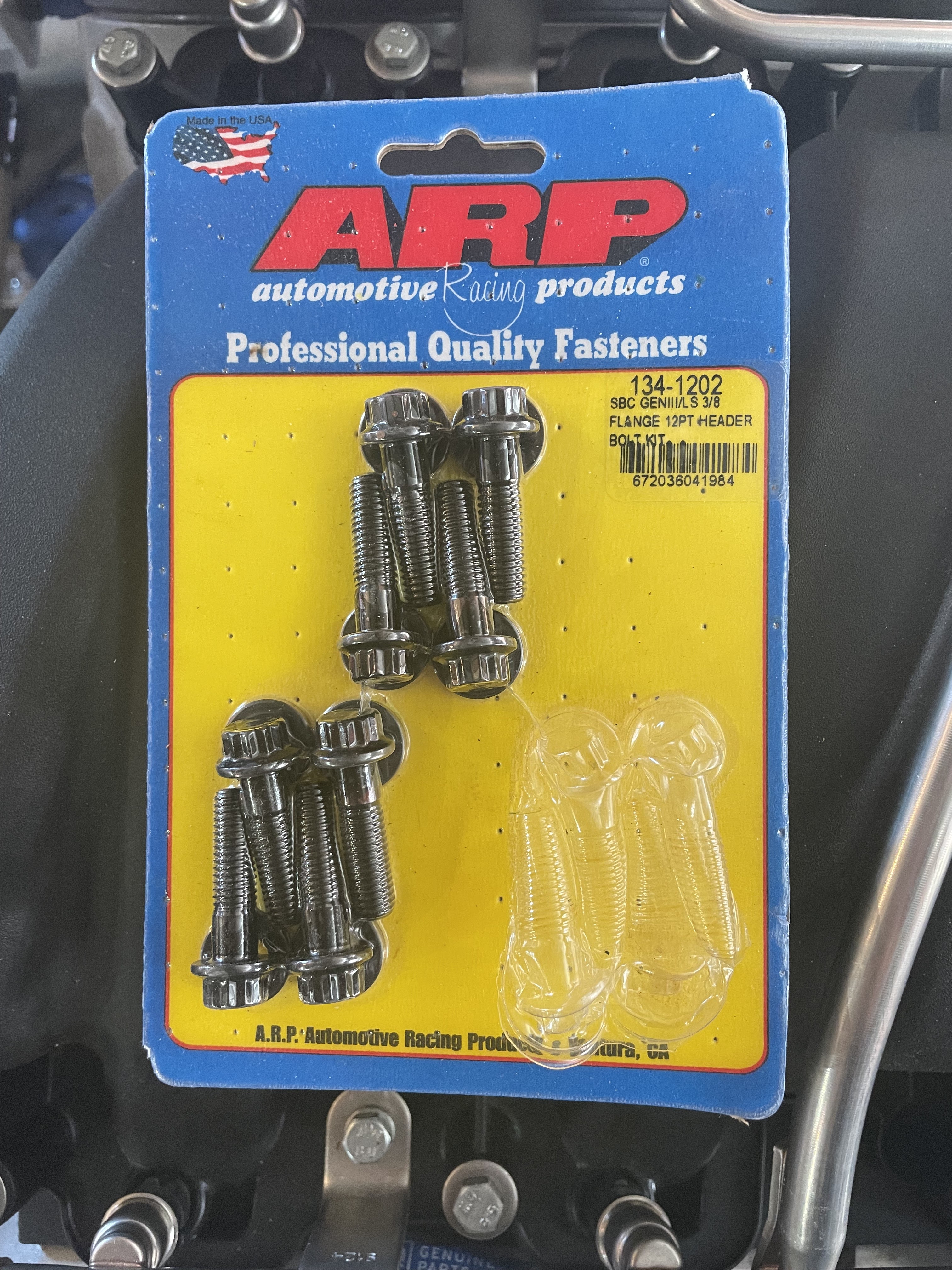
I decided to order some M12 cap head bolts, hoping that the smaller head dimensions would allow for wriggle room to allow me to get the bolts in.  I made the mistake of reinstalling the prop shaft so when the bolts arrived I discovered that I still couldn't get the bolts in with the prop shaft in situ.

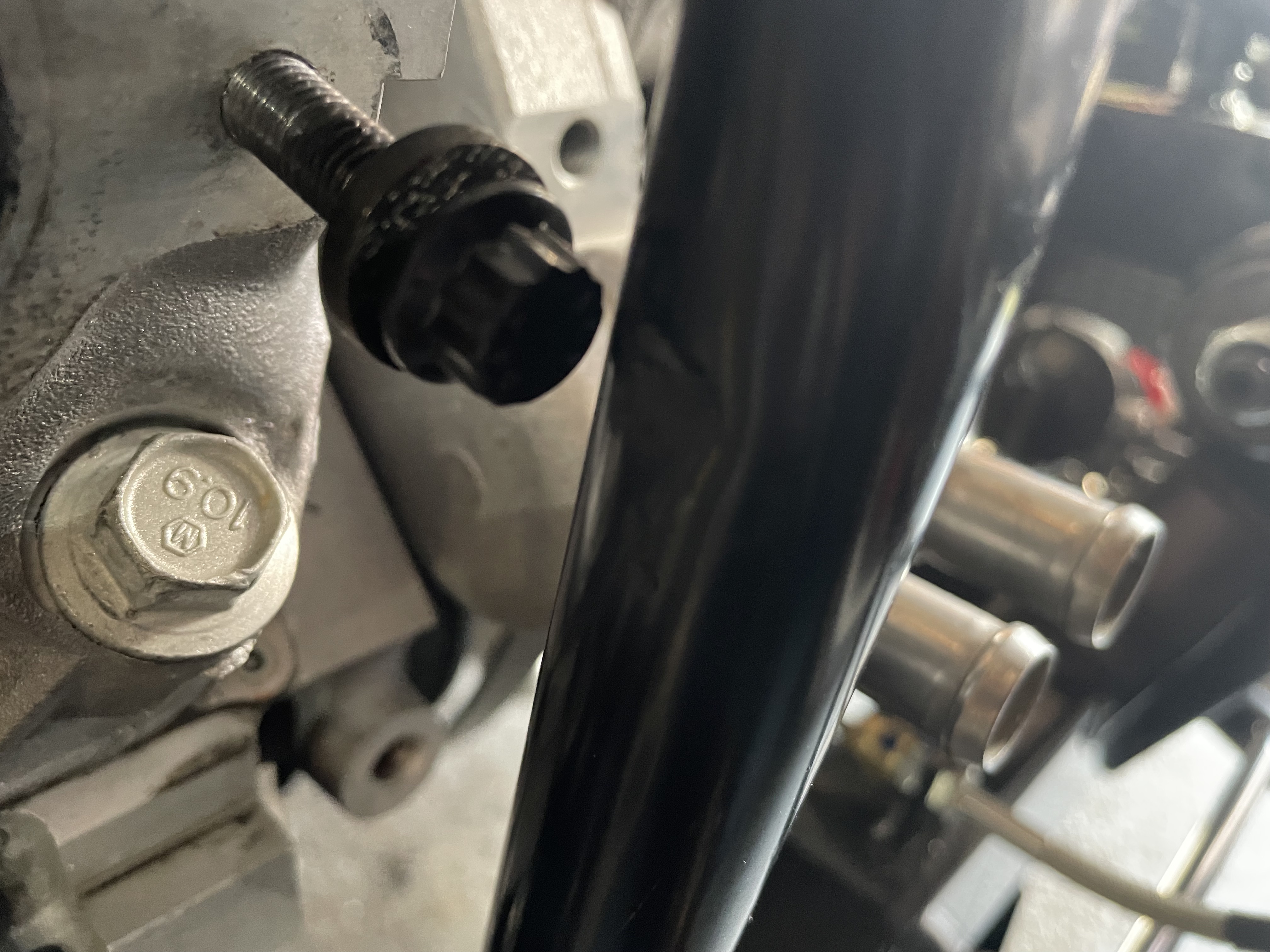
So out it came again and with some gentle persuasion from a soft-faced mallet, I managed to get the bolts into all three holes on the flange.  Then hopefully, for the final time, I reinstalled the prop shaft, lining up the bolts with the holes on the differential flange.  For once I had thought ahead and realising that I wasn't going to be able to install a bolt longer than 35mm in length and that the length of exposed thread was going to be quite short, I had ordered some thin Nyloc nuts at the same time as the cap head bolts.  For extra security I used some high strength threadlock on these nuts as well and, as I was unable to get a torque wrench onto the bolt heads, I tightened them up until my face went purple.

Bolts finally installed...

I rotated the propshaft a couple of times to make sure that the bolt heads didn't foul any of the parts of the UJ; it was close but there was clear air, so all good!


Sunday 5 March 2023

Heating & Cooling - Part 1 - Radiator and Fan

Installation of the radiator and cooling fan was a reasonably straightforward job.

I had purchased the AK aluminium radiator when I was up at their open day last September; as they had one in stock it seemed rude not to take it away with me!

I went for a Davies Craig 16-inch unit from Merlin Motorsport for the cooling fan.  This pulls a huge 2120cfm so it should keep my LS7 nice and cool.

The first step was to install the lower radiator mount, which is supplied as part of the AK chassis kit and is fitted with 4No. M8 bolts, washers and nyloc nuts.

Lower radiator mount fitted

There are two pins on the bottom of the radiator which are approximately 10mm in diameter and 20mm in length.  The proper way to sit the radiator onto the lower mount is to purchase some rubber top-hat washers; these slide over the pins and then locate the bottom of the radiator into the two 20mm diameter holes in the lower mount.  Other builders have used a variety of alternative solutions including a couple different diameters of rubber or silicon hose to create the stepped bushing.

I knocked up a couple of top-hat bushes from some 30mm nylon bar which hopefully will do the job.

Two bushes machined from some nylon bar 

Bush in place and keeping radiator from sitting directly onto lower mount

The upper radiator mount is attached to the top of the radiator using 2No. M6 bolts and washers and to the chassis using 2No. M12 bolts and washers.  I needed to clean out the threads in the chassis mounts with an M12X1.75 tap to remove the powder coating before the bolts would thread in easily.  The holes in the top radiator frame also needed some work with a file to remove the excess powder coat.  Initially, I assembled the top mount and radiator to check the fit but did not fully tighten any of the bolts.

The Davies Craig fan comes with four mounting feet that can be installed in several locations around the perimeter; I was hoping that by using the topmost and bottommost locations I could fix the fan to the upper and lower radiator mounts and not have to rely on zip-ties to secure the fan to the radiator.  

Fortunately, this was the case. I started with the holes in the upper radiator mount and drilled two 6mm diameter holes equidistant from the centre of the mount to match the spacing of the fan mounting holes.  I then loosely fitted the fan to the top mount with a couple of M6x25mm cap-head screws and reassembled the radiator and top mount with the fan to locate the bottom holes for the fan in the lower mount. I put some tape on the lower mount before reassembly and used a broken 6mm drill bit to mark the tape at the hole locations.  I then had to take the whole shebang apart again to drill the holes into the lower mount.  These ended up being lower than I had anticipated but still allowed enough space to install the cap-head screws; I might have had a problem with a normal M6 bolt.

I could then fix the fan to the upper and lower radiator mounts using the M6 cap-head screws, washers and some nyloc nuts.  I had to insert the cap-head screws the wrong way around from what I would have preferred to prevent the excess length of the screw from rubbing against the radiator; this meant that I had to tighten up the fan fixings fully before reinstalling the radiator.  Luckily there was enough play in the mounts for this not to be a problem.

Fan fixed to upper and lower radiator mounts

I could then reinstall the radiator, and fully tighten up the bolts securing the upper mount using a dab of blue Loctite for good measure.

A quick check showed that I had some clearance between the fan mounting bolt heads and the radiator so all was good!

Radiator back in and fully secured...

...with the cooling fan snugly sitting behind!

Free air between fan mounting bolts and radiator!

It's starting to look more like a proper car every day!!


Monday 20 February 2023

Engine & Gearbox Installation - Part 4 - It's in! (Eventually)

Finally, the day arrived when I was ready to install the engine into the chassis.

Everything was perfect, the sun was shining, the engine was suspended from my new engine crane, I had protected the tubular bracing on the chassis with some foam padding, my son had got out of bed to help out, and I had even remembered to alter the orientation of the thermostat housing on the front of the engine prior to installation.

The thermostat housing pointing the wrong way...

...and now the right way!

Unfortunately, things did not all go quite as planned.

From reading other build blogs, I was aware that, due to the tubular bracing on the AK Gen III chassis, the engine installation is made easier by getting the rear of the chassis as high as possible relative to the front.

To achieve the necessary attitude, all we would have to do was remove the axle stands supporting the front of the chassis.  However, when we tried to manoeuvre the engine crane into position, the legs of the engine crane would not fit underneath the front wishbones.  There was a short interlude, while we jacked the front of the car back up and supported it on axle stands adjusted to keep the front as low as possible while allowing the engine crane legs to pass under the suspension.  We then repeated that operation to avoid the engine crane legs hitting the axle stands...

Once the path was clear for the crane, actually getting the engine into place was quite easy.  The task was made much easier by using a load-leveller to be able to tilt the gearbox downwards.  It was then a case of inching the crane forward and slowly lowering the engine while raising the gearbox to get it into the chassis between all the bracing.

Almost there...

This was definitely a two-person task, especially as the gearbox was a very tight fit between the brake and fuel lines running along the inner chassis rails; there are a lot of lumps and bumps on the T56 gearbox that kept wanting to get caught up on the lines and a second person guiding the gearbox out of harm's way was essential.

Once we had the front pulley over the top suspension cross-member, we could get the engine down and level and sat onto the four engine bobbins that I had placed onto the chassis engine mounts prior to installing (these were just installed loose at this time).

We then supported the end of the gearbox on a trolley jack, removed the engine crane and lifting chains and had a well-earned cup of tea.

...and it's in!

After the tea break, the day took a slight turn for the worse.

Firstly I noticed that, despite our best endeavours, during installation one of the lugs on the gearbox had caught on and crushed one of the fuel lines; as a precaution, while raising and lowering the gearbox to install the gearbox mount, I removed the fuel and brake lines to avoid any further mishaps.  One piece of good luck was that the location of all my brake and fuel mounting clips all managed to miss clashing with the various sticky-out bits of the gearbox!

The next issue was that I could not get the tail shaft of the gearbox to sit centrally within the chassis due to one of the aforementioned lugs on the gearbox hitting part of the chassis bracing.  This needed me to break out the die grinder and a carbide bit and gently remove the offending lug.

Tailshaft not sitting centrally within chassis rails...

...due to this lug clashing with tubular bracing.

After some "light" fettling with the die grinder...

...offending lug is no more!

This now allowed me to get the gearbox aligned properly within the chassis and so the next task was to bolt the cross-member to the gearbox mount so that the holes in the chassis rail could be marked and drilled.

Except that the holes in my gearbox mount didn't match the holes in the cross-member.  When I ordered my chassis from AK my original plan had been to use a Tremec TKO600 gearbox and clearly that was what the cross-member I had was for.  For some reason, I had assumed the T56 cross-member would be the same, but on checking with AK, Jon advised that the mount was indeed different.  No problem, AK despatched me a new mount and I had that in my hands within the week.

New T56 cross-member (top) compared to TKO version (bottom)

Great - except that didn't fit either.  Firstly the holes still did not quite align with the holes in the gearbox mount.  Although they were only just out; so I reworked the holes slightly with a file to widen them out a bit until I could get the bolts into the gearbox mount.  But then I discovered that the cross-member was too wide!  Where it actually locates on the chassis is where the floorplans start to drop down below the level of the chassis rails and so the cross-member hit the floorplans and wouldn't sit tight up against the rails.  Also, I couldn't just cut down the new AK cross-member as the location of the cut would pass right through the holes for mounting to the chassis, so if I was to drill new holes there would not be much metal left between holes and the end of the cross-member.  

So I decided to order a length of 50mm wide steel bar stock and make my own cross-member.  I measured and drilled the holes for the mount first, these were 11mm in diameter to suit the bolts supplied with the gearbox mount.  I could then fix the bar to the gearbox and raise the gearbox until the bar was flat against the floor pans to mark where to cut it so that it would sit between the pans and against the chassis rails.  I also decided to only use a single 10mm bolt to fix each side of the cross-member but to install a threaded boss into the chassis rail (as per my fuel tank fixing) to provide a greater length of threaded connection.

Home fabricated mount (top) - spot the difference in length!

Threaded boss made from 20mm diameter bar

Cross-member installed and bolted into place

I will need to remove the mount again at some point in the future a) to powder coat or paint it and b) to facilitate reinstallation of the fuel lines.  But the engine and gearbox are finally in and this feels like a really big step forward in terms of progress on the build!