Sunday, 12 April 2020

Fuel Tank Mounting - Part 1

According to the AK Build Manual, the AK-supplied stainless steel fuel tank is fixed to the rear chassis subframe using M8 bolts; the fuel tank is hung under the subframe and bolted into the chassis through the mounting tabs welded onto the fuel tank.

Now petrol has a specific gravity of 0.720 (compared to 1.0 for water) and the AK fuel tank has a capacity of just over 65 litres.  The empty tank itself weighs approximately 15.2kg. So with when full, the tank and the fuel will weigh approximately 15.2 + 46.8 = 62 Kg.

There are 5 tabs on the AK fuel tank, each held up by an M8 bolt, so each bolt needs to take 12.4 kg.  The proof load of a single standard Grade 8.8 M8 bolt is 2120kg so there is a hefty factor of safety on the bolt even accounting for any dynamic factors.

However...

The rear box sections of the AK chassis that the tank is bolted to are only 2mm thick and an M8 bolt has a thread pitch of 1.25mm, so at best only two threads of the bolt are going to be engaged.  


When a tensile load is applied to a bolt it stretches slightly and the loading on each thread will be different; the first thread at the point of connection sees the highest load and decreases for each subsequent thread.  It is widely accepted that a minimum of six threads is required to establish a full strength connection (the first thread takes approximately a third of the load, the first three threads take approximately three-quarters of the load and the first six threads take essentially the whole load and beyond the first six threads the remaining threads are basically under no load at all).

There is some complicated theory behind all this...

No, I don't understand it either...
(Extract courtesy of Journal of Multidisciplinary Engineering Science and Technology (JMEST)

Basically, the outcome of all this waffle is that in order to ensure a full-strength bolted connection there needs to be a minimum bolt engagement of six threads and bolting the fuel tank to the AK chassis will only result in two threads being engaged (ignoring the fact that each bolt is actually only taking around 0.6% of its ultimate load capacity).  

My proposed solution to this is to create some bosses from 20mm diameter steel bar which will be tapped for a 20mm M8 bolt.  These will be installed into the rear chassis subframe around the fuel tank by drilling a 20mm diameter hole into the top of the rail, an 8.5mm hole in the bottom of the rail, inserting the bosses, which will be held in place by an 8mm bolt to maintain the position, while welding the boss into the subframe on the top surface.  See the diagram below

Section through rear subframe - fuel tank mounting boss

The fuel tank has sat in place on top of the rear subframe since the chassis arrived serving as a temporary shelf for various bits and pieces (I had put some duct tape over all the openings in the tank to prevent the entry of any detritus).

The first job was to remove all the crap off the top of the tank and even up its position within the rear subframe.


Fuel tank in position on top of the rear subframe

The rear subframe rails are 40mm wide steel box. I set some callipers to 20mm and scribed a line across each fuel tank mounting tab; even though the tab might not be sitting centrally on the subframe rail, this operation should ensure the resulting holes are all in the middle of the frame rails.


Scribing centreline of rear subframe rails on mounting tabs

I scribed the centreline of the mounting tab in a similar way and centre punched each of the tabs at the intersection point.  I then drilled a 4mm diameter pilot hole through each of the mounting tabs and through the top of the rear subframe rails. Stainless steel can work harden if it gets too hot while drilling, which can severely reduce the working life of drill bits, so I used plenty of cutting fluid to try and keep the drill bit cool.

Drilling pilot holes...

After removing the fuel tank, the next task was to attempt to drill a 4mm pilot hole in the bottom of the subframe rails perpendicular to the holes in the top of the rail.  I made a simple jig using an offcut of 50 by 25 rectangular steel section.  Using a pillar drill I drilled a 4mm hole through both sides of the steel section from the top; so in theory, these two holes should be exactly aligned and perpendicular to the face of the section.

Using the 4mm drill bit as a dowel I aligned this jig above the pilot holes in the top of the subframe rail and clamped the section in place.  I then drilled through the jig, the pilot hole and through the bottom of the rail.  Hopefully, all these holes will be fully aligned and the bottom hole will be directly under the top hole.


"Verticality" jig from off-cut of 50x25RHS

Next step was to open out the top holes to 20mm diameter using a step drill.  Step drills actually result in a proper "round' hole whereas normal drill bits produce a slightly triangular hole. I did check the length of the bit to make sure that I didn't inadvertently open out the bottom hole to too big a diameter; as if I had planned it perfectly, as the top hole opened out to 20mm, the 4mm step in the drill bit would be sat in the bottom hole!


2-20mm Step Drill Bit

Drilling out top holes - almost there...

...and done!

Unsurprisingly drilling out a 20mm hole creates a large amount of swarf and metal chips.  I used a magnetic probe to try and fish as much as I could out of the rails and then deburred the holes on the inside and out.  


20mm hole in the top of the rail with 4mm pilot (hopefully) dead centre below in the bottom of the rail.

The final step of this operation was to open the bottom pilot holes out to 8.5mm.

To make the mounting bosses I used a section of 20mm steel bar.  In theory, each boss needed to be 38mm long to sit flush with the top of the chassis rail.  However, I noticed that on one of the rails, the welded seam of the box section was on the bottom face. So to be sure I measured each boss individually by inserting the bar stock into each hole until it bottomed out and scribing the bar level with the top of the chassis rail.  I then cut all of the blanks for the mounting bosses (numbering them so I could tell which hole they were for).


Cutting 20mm Bar Stock using a Bandsaw

Five blanks cut to length and numbered

Now each blank needed to be drilled and tapped to take an M8 x 20 bolt.  I marked the centre point of each blank by setting my vernier callipers to 10mm and scribing three lines at roughly 1/3 intervals around the bar.  The intersection point of these three lines should be bang on in the centre of the bar.  This point was then centre-punched.


Centre point scribed and punched

I then set the blank into a drill press vice, checking to ensure it was perfectly square to the drill bit.  With a 4mm diameter bit, I then drilled a 25mm deep pilot hole into the end of each blank in turn.  Again I made sure to use plenty of cutting fluid and removed drill bit and cleaned out swarf every 4-5mm of advance.

The holes will be tapped for an M8 x 1.25 thread so the holes need to be opened up to 6.3mm diameter before tapping.  Again lots of cutting fluid and cleaning out every 4-5mm of advance.  As a final touch, I countersank each of the holes.


Opening Pilot Holes out to 6.3mm Diameter

Ready for Tapping

I then tapped the holes using an M8 x 1.25 tap.  As with the drilling I used plenty of cutting fluid and the recommended technique of 2 turns forward and 1 back to snap off the 'chip' caused by the tapping operation.  I also removed the tap occasionally to clean out the flutes.


Tapping in progress!

Final bosses - all tapped and ready to go!

I did a trial fit of the bosses into the subframe rails.  I was quite pleased to see that they all fitted flush with the top of the frame rail and that the hole in the bottom of the rail matched with the hole in the boss so that I could install an M8 bolt!


All fits perfectly!

I need to weld the bosses into the subframe rails to complete this part of the build.  I will address that operation at some point in the future. 

This is all probably massively over-engineered but I can sleep easy that no matter how much fuel is sloshing around the tank during hard driving conditions, the fuel tank is going to remain securely attached to the car!

Sunday, 29 March 2020

Rear Axle Strip Down - Part 9 - Hub Cleaning

In amongst getting various parts powder-coated, I have been progressing with cleaning up the rear hubs.

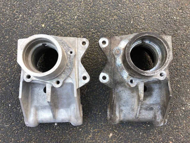
These are an aluminium casting and, after many years of service on the donor vehicle, were suffering from some heavy oxidation, particularly around the area where the steel brake back-plate sits, as well as having a good coating of general road grime.

The first step was to give the hubs a good soaking in a bucket of boiling water and some detergent - I used a couple of dishwasher tablets.  Vigorous brushing with a stiff nylon brush shifted some of the grime.  


One grimy rear hub ready for a bath...
...after a long hot soak and a bit of brushing

Note it is not recommended to use steel or brass wire brushes on aluminium as particles of the wire can embed themselves into the soft surface of the aluminium which can lead to future rust staining in the case of the steel brushes and severe corrosion in the case of the brass brushes especially if exposed to road salt.


After initial cleaning - note heavy oxidation around brake back-plate mounting flange

Next on the list of beauty treatments for the hubs was a session with the sandblaster.  Actually quite a lot of sessions.  Over many weekends...

The sandblasting gave reasonable but variable results.  Some areas cleaned up quite nicely - generally the flat areas.  The blasting removed the white aluminium oxide corrosion around the back-plate flange.  However, under the oxidisation the surface was quite pitted and, despite trying different media, the sandblasting did not remove all the of the oxidisation.  The resulting finish still had quite a lot of black oxidised aluminium in amongst the shinier areas.  This was the same case for some of the edges and recesses within the casting.


Hub after sandblasting - some areas of ingrained oxidisation remain...
The rear side of the hub - it was tricky to get sandblaster nozzle
 into the bottoms of all the recesses
Oxidisation still present in areas of pitted aluminium

The next treatment involved a liberal dousing with Frost Ali-Clean and a vigorous brushing with an old toothbrush.


Time for another scrubbing...

I have to say I was quite disappointed with the Ali-Clean.  It is supposed to be used on unpolished aluminium castings to clean and etch the surface.  Having applied the product as per the instructions and rinsed off with water, I'm not sure I noticed any difference in the finish.  The aluminium surface was no brighter and the areas of deep black oxidisation still remained.

This left me resorting to the electric drill and a brass wire brush (totally ignoring my own recommendation above....).


Recommendations?....more like guidelines...

This treatment did improve the finish slightly - but still did not remove all the areas of black ingrained oxidisation.  I even tried a further treatment of Ali-Clean (and I was still unimpressed...).


A before and after comparison - front side....
...and rear side.

When you look at the before and after photos, the cleaned hub does look significantly better than the 'before' version.  But I thought there was still room for a lot of improvement.  

Given that to get to this stage had probably taken me about 5 or 6 weekends and I had only 'cleaned' one hub, I came to the conclusion I needed a Plan B.

Plan B involved a trip to see the professionals, in this case, a local sandblaster in Braughing, RFI Screening.  They offered to vapour blast both hubs for the princely sum of £20 each.  In hindsight, I should have just taken this approach in the first place.  The results from RFI are amazing and I could have saved myself a lot of effort.


Hubs - straight back from the sandblasters...
...vapour blasting leaves a clean satin finish...
...even recesses on the rear are nice and clean.


Sunday, 8 March 2020

Differential - Part 4 - A strange sense of deja-vu...

In Part 3 of the rear axle assembly I had got as far as installing the rear wishbone tie and the differential tie bars.  I then undid most of that work and, at the back end of last summer, I stripped and re-powder-coated the wishbone tie.  So, one of the first jobs back in the garage for 2020 was to actually reinstall the wishbone tie.  The assembly was cunningly straightforward - almost as if I had done it before...!


Generous reapplication of copper grease on rear diff shafts...

Mounting Bracket re-installed...


Inboard Compliance Buffers back in place...


Wishbone tie re-installed and generously filled with copper grease...


Outboard Compliance Buffers also generously coated in copper grease...

With the outboard compliance buffers installed but not fully tightened I was able to jiggle (technical term) the ends of the differential tie bars into the wishbone tie and tap the bolts into place.


Ends of Diff Tie Bars lubricated with - you guessed it - copper grease...!

Reassembly complete!

The sense of satisfaction at getting this back together was slightly overshadowed by the realisation that I am now back to the same stage that I was last July!   But still, at least I have now done something useful on the car in 2020, so its progress of sorts.

I am still not happy with the length of the thread of the 7/16" bolts that hold the differential tie bars in place.  However, despite many hours of internet searching, it would seem that all UNC partially threaded bolts come with a standard length of the threaded portion (at 1.125 inches).  The only choice I seem to have to make these more aesthetically pleasing is going to be to cut the end of the threaded portion down a bit. 

Another job for the future...


An offensive length of protruding thread...

Sunday, 16 February 2020

Welding Practice

One of the main issues hampering my progress on Project Snake has been the state of my garage.  Never the tidiest person at the best of times, over the winter the garage has become a bit of a dumping ground.  I spent a couple of days having a very early spring clean which made things look a lot better.  However, I was still fed up of tripping over my welder(s) and gas bottles which always seemed to be in the way no matter where I put them.

Having added a TIG welder to the tool arsenal last year, I had decided that the disposable gas cylinders were a waste of money and invested in two Hobbyweld Plus size gas cylinders; a 5% C02: Argon mix for MIG welding and an Argon only cylinder for TIG welding.  

To tidy up the storage of the various welding paraphernalia and make it all a bit more portable (the MIG welder and gas cylinders are not exactly easy to handle) I decided to knock up a welding cart.  As well as freeing up some space I thought that it would also give me some good practice with the hot metal glue gun.

I produced a design for the cart in CAD and ordered the necessary lengths of steel section and plate.


CAD Design for Welding Cart

The bottom frame was made from 50x25 RHS while the rest of the frame was 25x25 SHS with 2mm Steel Plate for the shelves.  

Some various progress photos are shown below.  I think my MIG welding skills have improved somewhat after undertaking this project.  It is still very frustrating though, to lay down a series of really nice looking welds and think you've cracked this lark, to follow them up with the crappiest blobbiest bit of weld ever seen... Still, practice makes perfect.  Getting the torch angle right seems to be the key to getting a nice looking weld as well as a bit of a gap between the parts to be welded.


Steel for Bottom Tray cut and prepped
Looks nice - but a bit blobby...
Corner after welding and grinding
Bottom Tray complete
Steel for shelves cut and prepped
Shelf frame - various levels of weld quality...
Shelf top welded on
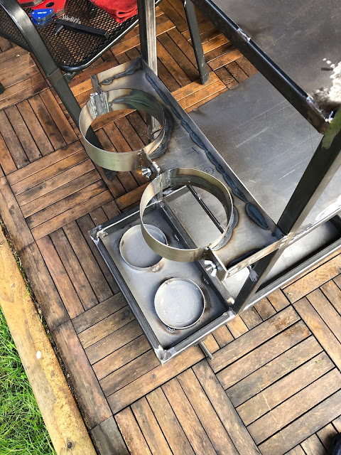
Using a gas cylinder to form Bottle bracket
Bottom bottle supports in place
Starting to take shape
Handle side cut and shaped...
...and end of handle notched to fit.
Upper bottle mount formed from 50x2mm steel strip
Tapping bottom tray for some casters
Heavy-duty casters - good for 200kg each!
Wheels and several coats of Hammerite Smooth

Have to say that I'm quite pleased with the final outcome.  A couple of bits need some fettling; the upper bottle stay doesn't quite tighten up with the bottles in place.  I also rushed the painting a bit, trying to beat Storm Ciara, and forgot to wipe all the grinding dust off the shelves before painting; this led to some vigorous sanding down and another two cans of Hammerite.  The finish is still not great but largely hidden by the welders, so it will do.

Cart loaded up...
...and ready for action

So that's tidied up some corner of the garage - time to get on with the rest of the Cobra build!!