Saturday 7 January 2023

Engine & Gearbox Installation - Part 3 - Avoiding Disaster

Before bolting the gearbox up to the engine I had a couple of modifications to make to the GM hydraulic throwout bearing.  

The first was to replace the factory inlet fitting with one that would allow me to connect up a -4 flexible braided clutch line.  This was a simple task of drifting out the roll pin securing the fitting, removing the original fitting and replacing it with a new one from Summit Performance.  To complete the job, I secured the new fitting with a new 4mm roll pin.

GM Hydraulic Throwout Bearing with original fittings

New -4AN inlet fitting (top) vs original inlet fitting 

New fitting installed and secured in place

Next up was to replace the factory bleed fitting with a HEL flexible braided remote bleed line.  The original attachment was unbolted very easily and it was a simple matter of screwing in the new remote bleed line with a copper washer and tightening it down firmly.  Now I can bleed my clutch without a) any special tools and b) without having to faff around under the car; the end of the remote bleed line will be fixed somewhere suitable in the engine bay.

Remote bleed line installed

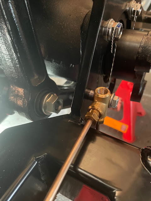
I ordered a braided clutch line from Merlin Motorsports which they made up to a length of 500mm and installed the fittings for me free of charge. I installed this onto the new -4AN inlet.

Braided -4 clutch line installed

The throwout bearing could then be bolted to the front of the gearbox, over the input shaft and with the two M6 securing bolts torqued to 35ft-lbs / 47.5Nm.

Throwout bearing installed on the gearbox

Just as I was preparing to fix the bellhousing to the engine, life decided to throw me another curveball.  In between the various tasks I had been keeping the engine hanging off the engine crane, but lowering it down to the floor in between jobs.  I didn't put the whole weight onto the floor, it was 'just' resting on some thick cardboard packing to protect the sump but most of the weight was still being taken by the crane.  In the event of any failure of the engine crane, I figured it was better to be closer to the ground than hanging in mid-air.

And then that failure occurred!

The engine crane I had borrowed was a mechanical rather than a hydraulic unit.  Raising or lowering the jib was achieved by hand turning a nut on the end of a long threaded rod which passed through a fixed threaded anchor block.

As I was merrily turning away at the nut with a ratchet to raise the engine up to install the bellhousing, I realised that while the nut was happily turning around, the thread in the anchor block was not moving at all.  In other words, I was perilously close to shearing the nut off the end of the threaded bar and dropping the engine fully onto the floor.

Coming close to disaster...

There then followed a short interlude while I endured the unexpected expense of buying a new 2T engine hoist from Halfords, waiting for delivery and then having to assemble said crane.  

With some help from my son, we managed to get some additional thick pieces of cardboard packing under the front and back of the engine, such that it was fully resting on the packing.  This gave enough slack to be able to unbolt the shackle holding the lifting chains to the original crane, whip it out of the way and swing the new crane quickly into place and attach engine chains to the new crane.  Hopefully, the only damage that I can see was caused when I rocked the engine slightly to one side to help hook it onto the new crane and dented the bottom of the oil filter.

With disaster averted I could now get on and install the aluminium bellhousing to the engine.  This needed tapping gently into place over the two locating pins on either side of the rear of the engine and then bolting up, tightening the bolts in an alternating sequence up to 35ft-lbs / 47.5Nm.  The fixing kit from Roadcraft came with M10 bolts for fixing the gearbox and bellhousing but also included two rogue M10 Cap Head bolts.  There are two positions on the bellhousing where the casting is such that clearance is very limited to get a 17mm socket over the end of a normal M10 Hex Head bolt so I assumed that was where the cap head bolts were to be used and these were tightened using an 8mm Allen-drive socket.

Bellhousing installed

Then it was just a simple (?!?!) of joining the gearbox to the engine...

As with most things on this build, this was not as simple as it should have been.  I placed the gearbox on a wheeled wooden dolly and adjusted the height of the engine so that the gearbox input shaft was level with the centre of the clutch alignment tool.  I pulled out the alignment tool and then moved the dolly forward to engage the input shaft into the clutch plates.  This took a bit of jiggling to get the splines on the input shaft to align with the clutch plates.  With a bit more jiggling I could then get the transmission to within about an inch of the bellhousing but couldn't get it to close up that last bit.

Almost there...

Over the course of the next 6 hours of wrestling with a 60kg lump of metal, I taught myself some new swear words as I repeatedly removed and tried re-engaging the gearbox into the clutch but still couldn't quite get it to fully join. I even persuaded my son to help out, but the gearbox continued to defy us!

Eventually, I decided that, because of the twin-plate clutch, the alignment needed to be absolutely spot on to allow the gearbox input shaft to engage in the pilot bushing.  So I pulled off the bellhousing, removed the clutch pressure plate and realigned the clutch plates.  This time I retightened the pressure plate bolts a couple of turns at a time in an alternating pattern to try and keep the clutch disks centred before torquing down to the final specification.  This did result in the alignment tool sliding in and out of the plates more freely than previously.

The next morning I renewed the battle, and after only a couple more rounds of wrestling, finally managed to get the gearbox to mate up with the engine!  I could then install the bolts to hold the transmission to the bellhousing and tightened them up to 35ft-lbs / 47.5Nm.  There was a small bracket on the gearbox breather hose, which I made sure to remember to secure with one of the transmission bolts.

Success at last!

Bracket holding breather hose

The rear transmission mount fixed in place

The last job before actually installing the engine and gearbox into the chassis was to reinstall the starter motor.  I had removed this to wrap it in some gold heat reflective tape from Funk Motorsport.  This should protect the starter motor from the heat from the exhaust headers and avoid any electrical issues due to heat soak

Starter wrapped in heat reflective tape


Thursday 29 December 2022

Engine & Gearbox Installation - Part 2 - Flywheel and Clutch

With the engine removed from its stand and hanging from an engine hoist, the next job was to install the flywheel and clutch.

Due to the engine sitting for some time, some light surface rust had appeared on the rear crankshaft flange.  I cleaned this up using a Scotch-Brite pad and gave the flywheel mounting flange a good clean with some brake cleaner, including the recess where the pilot bearing will be installed.

The directions for the ARP flywheel fixing bolts that came with my transmission installation kit specified the use of the included ARP lube under the head of the bolts with some Loctite 242 on the threads.

Loctite 242 (or Loctite 'Blue') is a medium-strength thread-locking compound.  There is an 'improved' product available, Loctite 243 (obviously), which has an improved oil tolerance and so doesn't require bolts to be scrupulously clean to be effective.  

Installation of the flywheel was straightforward; I applied a smear of the ARP lube under the bolt heads and on the top half of the thread plus a drop or two of Loctite 243 on the end of the thread.  I held the flywheel up against the crank mounting flange, screwed all the bolts in hand tight and then torqued them up in stages and in an alternating pattern to 85ft-lbs / 115Nm.

(The ARP flywheel bolts have a 12-point head.  While I could tighten the bolts up reasonably tight with a normal 14mm socket, when trying to torque them up to the final specification, the 14mm socket did slip on the bolt heads.  So rather annoyingly I had to order some 12-point sockets, which meant that I had to remove all the bolts and clean them up while waiting for the new sockets to arrive; had I left them in place, the thread lock would have cured and then when torquing the bolts that would likely have broken the bond rendering the thread locker useless).

Flywheel installed at 2nd attempt

I then tapped the pilot bearing into the recess in the crankshaft, using a socket as a suitable drift, until the front face was just flush with the front of the recess.  The pilot bearing is a roller-type bearing and was already greased.  I didn't add any extra grease to avoid excess lubricant being flung around in the vicinity of the clutch plates.

Pilot Bearing in place

I then gave the flywheel a good wipe down with brake cleaner and several paper towels to remove any traces of oil that were on the flywheel from the supplier (and my greasy mitts!) to protect it from rusting.  Once I had done that, I did it again, just to be sure!

The clutch installation was reasonably straightforward despite my opting for the twin-disc clutch setup.  I offered up the first clutch disc to the flywheel using the normal plastic clutch alignment tool that seems to come with all clutches.  I then needed to secure the adaptor which holds the floater plate for the twin-disc set up to the flywheel.  I put a couple of drops of blue Loctite on the securing bolts and torqued them to 25ft-lbs / 34Nm as per the instructions.  At this point, the bottom clutch disc can still spin freely between the flywheel and the floater plate.

Clutch discs have idiot-proof markings!

First (bottom) disc in place

Adaptor ring and floater plate installed

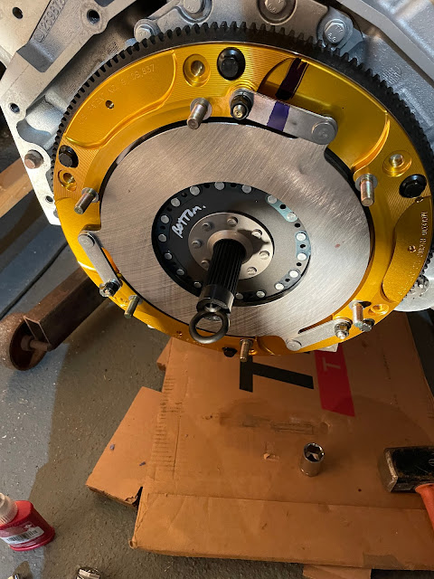
I then installed the second (top) clutch disc again paying heed to the orientation markings handily written on the disc.  This requires the removal of the clutch alignment tool so that it can be inserted through the top disc and then reinserted through the bottom disc.  So of course when it is removed the bottom disc drops and it was a bit fiddly to try and lift it back up and realign the plate so that the nose of the clutch alignment tool could slide fully into the pilot bearing and hold both plates in the correct place.  With that done I could place the pressure plate onto the mounting studs on the adaptor plate, taking care that the original assembly marks lined up, and secure the pressure plate with the mounting washers, spring washers and nuts.  The instructions are very clear not to use Loctite on these mounting nuts, so I didn't, and I followed instructions for torquing down the pressure plate nuts in an alternating pattern to 25ft-lbs / 34Nm and then 35ft-lbs / 47.5Nm.

Just to note as soon as the nuts on the pressure plate are tightened up even hand-tight, both clutch plates become fixed and will no longer move.  If the clutch alignment tool is not perfectly centralised and aligned, and the pressure plate nuts tightened then the plates might be slightly out of alignment which makes removal of the alignment tool incredibly difficult (but which also suggests that getting the gearbox input shaft back through the plates will be equally difficult).  I went through the process of tightening each of the pressure plate nuts by hand, around half a turn at a time, in an alternating pattern, while constantly moving the alignment tool in and out slightly to ensure that once the bolts were nipped down sufficiently and the plates fixed, that I could still slide the alignment tool in and out smoothly.

Pressure plate installed - looks too good to cover up!

The next step will be to join the gearbox and bellhousing to the engine.

Saturday 5 November 2022

Engine & Gearbox Installation - Part 1

My engine has been sitting in the corner of the garage on an engine stand and acting as a giant dust magnet since I collected it back in 2020.  Exciting times are ahead as I have reached the stage where I can seriously contemplate being able to install the engine and gearbox into the chassis.

There were a couple of bits that I was able to do before having to remove the engine from the stand to allow the gearbox to be fitted up.

First was to install a thermostatic take-off plate for the oil cooler.  I purchased a Derale LS Engine Oil Cooler Adaptor from Summit Racing.  This is a thermostatically controlled adaptor which allows the oil to bypass the oil cooler until the oil temperature reaches 180 degrees Fahrenheit.  It also includes two 1/8" NPT ports which can be used for oil temperature and pressure sensors for dashboard instruments.

Oil Cooler Adaptor 

The adaptor is installed by removing the cover on the side of the LS engine block above the oil filter.  There are two oil galleries behind this and the cover simply provides continuity of flow between the two.  

Location of the original cover plate above the oil filter

The cover simply provides a channel to connect the two oil galleries


As I do not have my dash instruments yet and therefore do not know the necessary senders required I sealed the two NPT ports in the adaptor with plugs which come supplied with the adaptor.  I used PTFE tape on the plugs just in case I end up running the engine without having installed the sensors.  

The adaptor also requires two AN adaptors to be installed to which the oil cooler lines can be connected.  The two ports on the top of the adaptor are -10 ORB fittings.  This, as I discovered, means that they are a -10 AN thread (7/8" UNF) while ORB stands for O-Ring Boss, meaning they need to be installed with an O-Ring seal.

I purchased two -12 AN to -10 ORB adaptors from Torques Products Ltd.  I lubricated the O-rings with some engine oil prior to installation and tightened both adaptors into the top ports.  

-12 AN to -10 ORB Adaptor

The adaptor plate itself also comes with two O-rings that need to be installed into grooves on the rear of the adaptor (I didn't lubricate these) before the adaptor plate is bolted into place with two M6 bolts which were torqued to 120inch lbf.  Note the inch rather than foot torque specification!! This equates to a mere 10ft lbf / 13.6 Nm so I could dig out my smaller torque wrench for this job!

O-rings installed on the rear of the adaptor

Oil Cooler Adaptor bolted in place

I also took the opportunity while the engine was on the stand to install the starter motor.  This will allow me to check the clearances between the starter pinion gear and the flywheel before the bellhousing is installed and makes that task pretty much impossible.

I was supplied a standard GM starter motor with my engine but I elected to actually install a Proform high-torque gear reduction starter motor.  This type of starter has a lower electrical power demand but still produces enough torque to spin over higher-compression engines.  The Proform starter also can be "clocked" in three different rotational positions to allow more clearance of the solenoid from exhaust pipes or other components if necessary.

Standard starter (top) vs High Torque starter

The three bolt positions on right allow starter body to be rotated relative to mounting plate

Installation of the starter was straightforward being held in place by just two bolts.  I haven't torqued these up to final specification at present just in case starter needs to be removed to add shims to get the correct clearances to the flywheel.

Starter motor in place

The last job before lifting the engine off the stand was to bolt on the engine mounting plates.  These were fixed in place with 4No. M10x25 bolts and M10 washers each side.  For added peace of mind I put a drop of Loctite 271 on each of the bolts before installation.

Engine mounting plate in place

With those jobs done its time to get the engine crane out and lift the engine off the stand to allow flywheel and clutch to be installed.


Thursday 27 October 2022

Gearbox Part 3 - Electronics!

Back in the good old days, a manual gearbox was a simple matter of some magic mechanical coggery hidden in a case, with an input shaft, an output shaft and some sort of shifting mechanism to change between the (then four) gears.

Clearly, things have moved on, and not just in the number of available gears.  After unboxing my Tremec T56 gearbox I noticed a number of electrical connectors dotted around the casing.  After some internet research, I discovered the following:

The connector at the front left-hand side of the gearbox casing is for the reverse light switch i.e it activates the reverse lights when reverse gear is selected.

Reverse Light Connector

The connector at the rear left-hand side of the casing is the VSS output (variable speed sensor) which is used to send a signal to an electronic speedometer (there is also a mechanical speedometer output on the opposite side to the VSS connector - as I will be using the VSS option the mechanical output needs removing and replacing with a blanking cover).

VSS Output Connector

Mechanical Speedo Output (will be removed)

Finally, the connector at the rear of the casing behind the shifter location is for the reverse lock-out solenoid.  This is a safety feature and prevents inadvertent selection of reverse gear while the car is travelling forward at great speed; on production cars the solenoid is automatically controlled by the car's ECU to only allow reverse to be selected when the car is stationary.

Reverse Lockout Solenoid Connector

So how to control the reverse lockout solenoid?

The reverse lock-out is apparently just a spring with a ball-bearing detent.  This can be overcome with brute force but clearly is not recommended by Tremec and could lead to damaging the gearbox.

Other solutions suggested involve the use of a microswitch on either the clutch pedal or brake pedal to operate the solenoid - on the basis that you would probably have your foot on one or the other or both when preparing to select reverse gear.  The downside is a) the solenoid would operate every time the brake or clutch pedal was pressed so possibly leading to premature wear and failure and b) if the brake or clutch pedal was pressed at 100mph (not unlikely) the solenoid would operate and so it would still be possible to select reverse gear at a high forward velocity, which kind of defeats the object of having it in the first place...

There are several aftermarket manufacturers of a small black box of tricks which simply does the job of the missing OEM ECU and, using the VSS output, will only activate the solenoid when the car is stationary or travelling very slowly (typically less than 3mph).  This would probably be the most sensible option.  The downside is that these kits cost several hundred dollars (plus good old import duty and shipping).

Fortunately, the CANEMS ECU that I bought as part of my engine package does have the ability to be programmed to operate a switched output based on the VSS output i.e to only operate the solenoid when the car is stationary.  Will need a bit of loom surgery to accommodate but in theory, all looks quite straightforward.

The final piece of this story is to obtain the various electrical connectors to join up with those on the gearbox.  I bought a kit from Bowler Performance Transmissions in the States; this included all the various connectors each with a short wiring pigtail and a billet blanking plate and bolt for the mechanical speedo output.  I ordered online and was quoted some ridiculous price for shipping (more than the price of the kit) but when I rang Bowler they were able to come up with a far cheaper shipping method.

Contents of the Bowler T56 Install Kit

So looks like I will have some fun when it comes to trying to add these into the wiring loom later but for now, I can get cracking on hooking the gearbox up to my engine and getting closer to installing it in the chassis.


Monday 17 October 2022

Brake Lines Part 5 - Rear Brake Lines and Fittings

I've been putting off completing the rear brake lines as the run from the bracket on the chassis leg at the front of the car to the position of the 3-way connector at the back of the car is rather complicated; not only does it have to follow the bends of the chassis along the transmission/prop shaft tunnel, but it also needs to partially run along the top of the chassis rail and then drop down to continue along the side of the rail.  It's also a single length of pipe of around 1.9m that needs 8 bends put into it accurately so that it fits into the front union and rear 3-way connector.

The other factor was my desire to use my over-engineered brake clips to secure the pipe run and try to come up with locations where these could be installed and maintain fixing centres of less than 300mm.  There is a cut-out in the chassis rail to give clearance to the starter motor which is greater than 300mm.  I was originally thinking to run the pipe down this recess and secure with a clip on the sloping face so that I could achieve the required fixing distances; I went and had a look at Richard Chippendale's build once he had got his engine installed and I am sure there was enough space.  However, as time moved on, I became less confident that this would work (the recess is there for a reason, right?).

My original thought for routing the rear line (in red)

In the end, I concluded that I was going to have to stick with the tried and tested AK routing for the rear brake line and would have to suck up using some P-clips or similar to secure the pipe run along the top section of the chassis rail.

I also decided not to bother with my previous CAD model approach for determining the lengths/bends in the pipe run; with the number of bends and changes of direction (and my limited CAD design abilities) modelling the pipe was just going to take too much time.

Time for PAD (Plywood Aided Design)!

I clamped a piece of 600x1220 plywood to the underside of the chassis and traced the outline of the chassis rails onto the wood.  I could then offset a line, representing the centre of my brake clips, and draw out the line of the pipe run in a handy 1:1 scale!

Time for some Plywood Aided Design...

With some additional 1:1 sketches for the bends down the chassis rail, I was able to measure the length between all the bend vertices and calculate the overall length of the pipe required and the position of my marks for bending.

I cut an over-long section of 3/16" brake pipe and started with the flat bends in the middle of the pipe run, along the transmission tunnel.  This section was bent up and secured in place on my plywood template using some push-in plastic clips.  This helped secure the pipe in place so I could make sure I got the correct orientation of the next bend.

A perfect fit!

I also remembered to put the brake fitting on the rear end of the pipe prior to forming the brake flare!  

Next, I made up the short section of straight pipe at the offside rear, from the flexible brake pipe to the 3-way connector at the rear.  This was a dead straight piece of pipe with the dimensions measured from my 1:1 sketch so what could go wrong?  I don't know what I did but I clearly measured something wrong, such that the first attempt was too short by a country mile!  The second attempt was much better.

Perfect - at the second attempt...

I then installed this section of the pipe and the 3-way union which allowed me to hold the rear of the long rear pipe run in place.  I could then check and double-check the location and measurements for the pipe bends up and over onto the top of the chassis leg before tentatively forming the bends.

Pipe run held in place temporarily and bend over the chassis formed

Where the pipe runs along the top of the chassis rail adjacent to the starter motor cut-out/recess I have elected to use some plastic push-in pipe clips from Car Builder Solutions; these have a small plastic collar, which is inserted into a 6mm diameter hole, the clip then pushes into the collar and clips into place.

Non-over-engineered Plastic Pipe Clip

The next task was to bend the pipe back around to meet up with the union on the front chassis leg.  Again I was sure to install the pipe fitting prior to forming the flare on the end of the pipe and making the bend.

The last couple of bends and everything lined up perfectly!

The last pipe-bending operation was to form the section of pipe from the 3-way connector that passes over the top of the differential nose and joins to the nearside flexible brake pipe.  I had modelled this section of pipe in CAD so was able to print out a sketch with all the necessary dimensions to enable me to accurately bend this into shape.

Last section of pipe bent up and in place

With all bending done I could fix the long run in place with five of my bespoke brake clips (which will also be used to hold the fuel return line to the tank in place).  This fixed the position of the 3-way brake union and using a transfer punch I could locate the centre of the fixing hole on the plate across the rear of the AK chassis.  

Unfortunately, the centre point of this hole was not ideal from a drilling and tapping perspective.  The tubular stiffening cage of the AK Gen III chassis provides enough of an obstruction to prevent being able to use a normal drill.  I had already discovered the need to purchase a 90-degree drill to be able to drill the holes to fix the brake clips along the inner legs of the chassis so this was pressed into action again to drill a 6mm hole.  

However, when it came to try and tap the hole for an M7x1.0 thread it was impossible to rotate the tapping wrench sufficiently to get the tap to start to bite in the hole.  I had to start the tap with a pair of pliers and then do my best with an adjustable wrench to continue trying to tap the hole.  It got to the point where I couldn't turn the tap anymore for fear of snapping it and so I couldn't tap the hole to the full depth.  Thankfully I managed to get enough thread cut so that I just needed a washer under the head of the bolt to get the union tight up against a spacer and all the pipes lined up where they should be.

3-way Brake Union fixed snugly in place

The last job was to drill a couple of holes to insert some plastic brake clips to secure the pipe over the top of the differential nose.  Again this job required the use of the 90-degree drill and several 6mm drill bits and I managed to snap one of the bits whilst drilling the second hole; this left a ragged hole which simply blunted any drill bit which I attempted to use to subsequently complete the hole.  In the end, I had to give up and drill a new hole just to the side of my original attempt.  

Pipe over differential clipped in place

I will, at some point soon, remove all the brake lines, blow them through with compressed air to make sure all detritus is removed and then fully tighten up all the unions for the last time.  I will also put some thread lock on the bolts securing my custom brake clips to the chassis for added peace of mind.

But for the moment the brake lines are done!


Wednesday 28 September 2022

Brakes - Part 3 - Rear

 The rear calipers supplied AK Big Brake upgrade kit usually are designed to work with 295mm diameter by 10mm thick rear discs (non-vented).  As my donor car came with 305mm diameter by 20mm thick vented discs I was keen to retain this setup.  Fortunately, HiSpec (who make the upgrade kits for AK) were able to adapt the spacer between the two halves of the caliper to accommodate my larger and thicker discs.

As at the front, the new rear calipers are larger than the original donor single-pot items but weigh in at 1.7kg compared to the 2.06kg of the originals.  They also benefit from two pistons per side to improve the application of braking pressure to the pads.

Size comparison - original caliper looks very sad in comparison

2 pistons per side compared to the single piston original

New Ferodo pads (left) are similar in size to the originals

I ordered some new rear discs from EBC brakes.  I went with their USR Sports Series disks which are slotted and come in a black thermic coating to help combat corrosion.

As with the front calipers, the kit comes with new brackets and bolts to fix onto the rear hubs onto which the callipers are attached.  I fitted these and torqued the mounting bolts to 60Nm/44lbf-ft.  

New caliper mounting blocks and bolts - with confirmation that they have been adapted for 305 x 20mm discs

I inserted the brake pads before installing the calipers - again this could be done with the caliper on the car but I figured it would be easier to do it on the bench (or floor as it turned out).  For the rear pads, the kit comes with some springs which need to be slid onto the outer edge of the pads.  I remembered to give the back of the pads a smear of copper grease before inserting them into place.  They are secured by two pins held in place with R-clips, the springs on the pads need to be eased under the pins as they are inserted to hold the pads into place.

Brake pad spring installed on the outer edge of pad...

...and a smear of copper grease added to the rear of pad...

...before pads inserted into caliper and held in place with retaining pins.

The last task before the final installation of the calipers was to adjust the handbrake adjusters on both sides so that the handbrake pads were just rubbing on the inside of the discs (although I think some further adjustment may be required at a later date). I could then bolt the calipers to the mounting blocks and torque the bolts up to 60Nm/44lbf-ft.  

Rear brake discs and calipers done!

And with that, I have probably reached the stage of the build that I was originally hoping to get to at the end of 2019...so only 3 years behind schedule!