Showing posts with label Clutch Line. Show all posts

Monday 9 September 2024

Body Preparation - Part 2 - Pedal to the Metal

AK recommends fitting the pedal box to the body before installing the body on the chassis.  Most builder's blogs also suggest that installing the brake servo and master cylinder is a much easier job if done with the body off the car.  So that was my next job!

I obtained my brake servo unit, from a Rover 200, via that renowned internet auction site.  When I was looking for this, there seemed to be none available in the UK and I ended up having mine shipped from Lithuania!

My unit arrived looking in not too bad a condition.  Importantly it also came with the grommet and the spigot for attaching the engine vacuum line.  I gave it a quick scuff-up with a scotchbrite pad, masked up the bolt threads and bellows and applied a couple of coats of primer, followed by some matt black spray paint.

The servo unit was given some gentle abrasion...

...followed by a couple of coats of primer...

...and some black spray paint

Looking almost as good as new!

The master cylinder from a Rover 25 or Rover 200 is also needed.  However, as I had opted for the big brake upgrade kit I needed to also upgrade the master cylinder.  

This got a bit confusing for a while as I really struggled to find the right part.  AK suggested that the required bore of the master cylinder was 22.7mm as opposed to the standard Rover 25/200 component, which has a 22.2mm bore. This meant that I needed to search for a master cylinder from a Rover 220 Turbo model, which according to Jon at AK is easily identifiable as the brake pipe outlets on the master cylinder point to the outside of the car as opposed to pointing toward the engine bay.

I completely failed to find any Rover master cylinders with a bore of anything other than 22.2mm and the majority seemed to have the outlets facing the engine.  In the end, I bought a brand new unit from TRW, which had the outlets on the correct side, but still had a bore of 22.2mm; so fingers crossed it works!

New master cylinder unit - bore 22.2mm

The master cylinder was bolted to the servo unit using some M8 Nyloc bolts, remembering to install the rubber O-ring between the master cylinder and the servo.

Servo and master cylinder

In hindsight, it might have been easier to install the servo into the engine bay and then bolt the master cylinder on.  There is not a lot of space between the pedal box firewall and the inner wheel arch.  It required a lot of careful jiggling around, taking care not to scratch the stainless steel engine bay cladding before I managed to get the servo and master cylinder in place.

In place - and it's not coming out again!

I'm running a 'Drive by Wire' (DBW) throttle set-up so I needed to drop the GM DBW throttle pedal (which includes the position sensor and electrical connector) off with AK so they could modify their normal pedal box and install the new pedal.

Modified Pedal Box with DWB Throttle Pedal

I had hoped that I could use the studs from the brake servo to 'hang' the pedal box off while installing it to make life a bit easier.  Unfortunately, the weight of the box and its centre of gravity conspired against me.  So installation of the pedal box is definitely a two-person job.

The pedal box is secured to the firewall with M8 bolts.  I bought some stainless steel Allen-head bolts, which as they will be visible in the engine bay, I treated to a bit of an extra polish to match the shiny engine bay cladding.

Shiny!

With me standing in the engine bay, trying to hold the pedal box against the firewall with my fingers through the hole for the clutch master cylinder and holding an Allen key into each of the bolts, and with my son lying in the driver's footwell with a socket and extension bar, we did manage to get the pedal box installed into place and secure the brake servo in place.  It is impossible to get a socket onto the upper bolts, so we had to resort to a spanner for those.  

While my son was trapped in the footwell I also took the opportunity to install the clutch master cylinder.  I bought a Girling unit with a 0.75" bore from Car Builder Solutions.  Again this was installed using 2No. shiny 8mm Allen-head bolts. 

Another "easy" job completed...

...and as seen from the inside!

And with that done, I am one step closer to getting the body on! 


Monday 10 August 2020

Clutch Line

Bending and fitting the clutch line followed much the same process as for the brake lines.  

The clutch pipe is formed from 1/4" diameter copper / nickel pipe.  This was much easier to bend using my pipe bending tool - as it was the correct diameter for the channel in the tool and all the bending marks were for the correct sized pipe. Although bending the pipe by hand, using the pipe bending pliers, took a bit more physical effort than the brake pipes; thankfully I only needed to form one bend with the pliers.

The overall length of the clutch line was around 1.8m so that was a bit of fun to try and handle and get all the bends in the correct plane.  I used the measurements from my CAD model, made the correct allowances for the bend gain (based on 1/4" pipe) as done previously for the brake pipes.  I was pleasantly surprised to get the whole section of pipe bent up correctly the first time!

I must have measured something wrong, however, as the pipe didn't quite reach the bulkhead fitting on my chassis bracket - fortunately, this was an easy fix by simply reversing the bulkhead fitting in the bracket!

I made up another small bracket to hold a further bulkhead fitting on the inner nearside chassis rail (powder coated candy red of course!).  Eventually, there will be a short flexible pipe from this fitting to the clutch slave cylinder that will be mounted on the side of the gearbox.  I worked out roughly where to fit the bracket from looking at Richard Chippendale's rolling chassis on a recent progress visit!

I also made up some additional mounting clips, with just a single hole, to hold the clutch pipe securely along the inside of the chassis rail.

That concludes all the pipes for the front end - next is to tackle the brake pipe run to the rear brakes.

Bracket made up to hold bulkhead clutch fitting

The bracket after powder coating...

...and with bulkhead fitting in place (note I bought some brass locknuts!)

Bracket and fitting in place

Passenger side clutch pipe routing

Driver's side routing

Termination at chassis bracket - one more pipe to go!


Sunday 19 July 2020

Brake Lines Part 4 - Front Brake Lines and Fittings

So with elementary bending and flaring mastered, knocking out the front brake pipes for the Cobra should be a doddle right...?

I started by marking out the positions of the mounting clips and the position of the 3-way brake union on the offside inner chassis rail (all based on my CAD brake pipe routing).

Fixing points for brake clips/unions marked using masking tape

I started with forming the short pipe that runs from the front off-side brake Flexi to the 3-way union.

I realised at this point that my brake-bending tool was completely useless for this pipe as it is impossible to form a bend on the pipe anywhere closer than around 50mm away from the flared end of the pipe; any closer and the brake fittings get in the way and prevent alignment of the pipe within the bending tool.

I resorted to using a couple of offcuts of nylon sheet with a 3/16 hole drilled through them to hold the pipe in the vice and using a piece of 25mm dia steel bar stock cut down with an angle grinder to bend the pipe around.  I checked my bending against a 1:1 drawing of the pipe from my CAD model (sad, I know) and the result was surprisingly close and with the pipe screwed to the Flexi and to the 3-way union the centre of the mounting hole was bang on with my mark on the masking tape.  Result!  Although this turned out to be a bit of beginners luck...

Forming bends close to brake fitting using a 12.5mm radius former

Checking the bending against CAD drawing

Pipe in place...

...and mounting hole aligned perfectly with planned position

Next was the longer pipe run from the 3-way union round to the nearside brake Flexi.  This was a step-up in difficulty level from the previous pipe, being just under 900mm long and needing 8 bends of varying angles (from 30 to 90 degrees).  This is where being able to position the bends exactly where you want them on the length of the pipe becomes important and brings into play those additional marks on the bending tool.

And just to complicate things, when you form a bend in the pipe, it actually stretches along the outer side of the bend, so the pipe actually gets longer - which of course you need to take account of, to be able to position the bends accurately! 

By way of example, the sketch below shows an example length of pipe.  Taking the dimensions between the vertices at each bend (the intersection of the centre line of each leg of the pipe) would suggest that the required length of pipe would be 100 + 100 + 70.71 + 60 = 330.71mm.


However, this would not take account of the pipe stretching when forming the bends so the final pipe would not be the exact dimensions required.

There is some complicated method for working all this out but I stumbled across a table in the owners manual for the extremely expensive Swagelok pipe bender on the internet, which has a handy table of bend gain adjustment factors for pipes from 1/8" (3mm) to 1/2" (12mm).  Basically, this all boils down that for 3/16" pipe, the adjustment factor for a 90-degree bend is 7mm, for a 45-degree bend is 1mm and for a 30-degree bend is basically insignificant.

Measuring out for the above example would then result in the following:
  • P1 would be measured 100mm from the Start of the pipe
  • P2 would be measured 100 - 7 = 93mm from P1 (allowing for the previous 90-degree bend)
  • P3 would be measured 70.71 - 1 = 69.7mm from P2 (allowing for the previous 45-degree bend)
  • The End of the pipe would then be 60 - 1 = 59mm from P3 (allowing for the 45-degree bend as before) 

So actual length of pipe to be cut to achieve the final dimensions in the above sketch would be 100 + 93 + 69.7 + 59 = 321.7mm.

(NOTE -  that this assumes that the pipe is bent from left to right i.e P1, then P2 then P3 - if you were to bend the pipe in the reverse sequence you would actually have different lengths for various sections -  End-P3 (60mm), P3-P2 (69.7mm), P2-P1 (99mm) and P1-Start (93mm) - although the overall length of pipe would be the same at 321.7mm)

So with this exciting theory all worked out, I could take the dimensions of the brake pipe from my CAD model, work out the overall length of pipe needed and mark out the positions of the individual bends making due allowance for the bend gain.

Position of bends marked out

Depending on the required angle of bend, the pipe is positioned in the pipe bender, with the bend position mark aligned with the respective bending mark.  The photo below shows a pipe set up for a 90-degree bend - the start of the pipe is to the left side of the tool, so the position mark is aligned with the 'L' on the rotating arm.  (If the pipe is inserted into the tool with the previous bend or position mark on the right-hand side of the stop edge then the position mark would be aligned with the 'R'.  

Pipe positioned in bending tool - the start of pipe is to the left of the rotating arm so the 'L' mark is used to position the pipe for bending

Perfect 90-degree bend - note I could not perform the first bend using the pipe bender due to the small distance from the pipe fitting

One section of pipe with perfectly positioned bends (except for the last bend close to the pipe fitting on each end)

OK, it wasn't as straightforward as that. 

On the first attempt, I failed to follow BRAKE PIPE TOP TIP 1 and produced a perfectly bent-up length of pipe with a brake fitting missing off one end...

Which brings me to BRAKE PIPE TOP TIP 2.  Make sure before bending any section of pipe that the brake fittings are on the correct side of the bend as they will not pass over the bend once it is formed - again, you may ask me how I know this...

Hmm...something's missing...

I think it took about four attempts to get this pipe right and I wasn't helped by my beginner's luck deserting me when trying to form the tight bends needed at the ends of the pipe adjacent to the fittings.  My subsequent attempts to form these bends using the method I described above resulted in the bends being too large a radius or just in the wrong place which completely cocked up the alignment of the fittings on the pipe with the fittings to which they were supposed to attach to!

In the end, I had to bite the bullet and bought another set of pipe bending pliers from Frost.  These are supposed to form neat bends with a radius of around 15mm with just a twist of the wrist!  Well as usual - not quite.  You can form bends by gripping the pipe with the pliers and giving it a twist, but it does tend to distort the section of pipe ahead of the bend so rather than being straight, the pipe ends up with a distinct curve in it. Also where the pliers grip the pipe, they left a quite deep gouge which didn't look very professional at all.

Eastwood Brake Pipe Pliers - with channels for 3/16" and 1/4" pipe

Form a nice bend and distort the adjacent section of pipe with a flick of the wrist!

My solution was to hold the pipe in the pliers and with both thumbs push the pipe around the bending channel.  Hard work on the thumbs but it gave the desired result.  A bit more geometry was needed as well to work out the actual start point of the bend to know where to grip the pipe with the pliers.

With this section of pipe now bent up to my satisfaction I could check that the positions of for the brake mounting clips were in the correct place and then drill and tap the chassis to allow clips to be fixed in place.  The eagle-eyed will notice that I have powder-coated the backing plates of my brake clips - well I needed to do something to stop them rusting!

Final Brake Mounting Clip

Backplate fixed to chassis with M5 x 8mm Cap-head bolt

Pipe and Clips in place - nearside...

...and offside

The 3-way union was bolted to the chassis using an M7x30 bolt.  The union needed to be spaced off the chassis slightly.  Most people seem to use a number of washers to do this but I made up a small spacer from some 12mm dia stainless steel bar, which I drilled a concentric 7mm dia hole down the middle of, and cut off the required spacer thickness.

12mm dia stainless steel bar stock

Pilot hole drilled down the centre of bar stock...

...before opening up to 7mm dia

3-way union bolted in place with spacer

The final step to complete the front brake lines was to make up the short length of pipe running from the 3-way union to my fabricated bracket.  This turned out to be the most awkward section of pipe to make, although if I wasn't so fussy about how neat it should look, it possibly wouldn't have taken so many attempts...

The main issue was trying to form the two 90-degree bends back to back (with one at 90-degrees to the other) adjacent to the 3-way union.  The first bend needed to be very close to the union, with the second needing to be right at the end of the first bend.  Despite several attempts (more than two but less than fifty...) I couldn't get the two bends to look neat and or get the overall pipe length at both ends.  

The purchase of the second set of pipe bending pliers helped somewhat but in the end, I settled for angling the pipe slightly coming out of the 3-way union and making the second bend a 45-degree angle which made things slightly easier to bend.

Which brings me to BRAKE PIPE TOP TIP 3 - when you have had dozens of attempts to make up a section of pipe and finally create the perfect back to back set of bends, do not rush to make the next bend in the pipe and form the bend in the wrong direction from that required...yes you may ask me how I know...

After a couple of attempts...

...finally managed to bend up final section of pipe!


Pipe route needs to allow for 1/4" clutch pipe to run between pipe and tube stiffener

So that's all the front brake pipes bent up and sorted.  I will blow all the pipes through with a compressed air line before tightening up all the unions.  Now to bend up the clutch pipe to complete all the pipework at the front end.

Saturday 13 June 2020

Brake Lines Part 3 - Going round the bend...pack the distress flares

With the brake/clutch pipe routing finalised and the bulkhead bracket in place, it was time to master the art of bending and flaring brake lines.

To form the brake line flares I have invested in a heavy-duty flaring tool from Car Builder Solutions.  This is a vice mounted tool with the advantage that it came with the dies and punches to form male and female flares in both 3/16" and 1/4" pipe.

Brake Flaring Kit from Car Builder Solutions


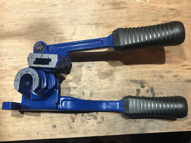
I also bought a Brake Pipe Bender from Frost Restoration.  There are many similar tools available but I liked the look of this one as it seems to fully support the pipe around the whole bend during the forming operation, avoiding any risk of kinking or crushing the pipe.  Again it also has the advantage of being suitable for 3/16" and 1/4" pipe.  More on this later...

Pipe Bending Tool
Pipe Bending Tool

I also purchased a 25ft roll of 3/16" copper-nickel brake pipe from Car Builder Solutions and a slightly more expensive 25ft roll of 1/4" copper-nickel pipe from Frost for the clutch line (unfortunately Car Builder Solutions don't sell 1/4" line) and the following brake fittings from Automec.


I did a few test flares on a few short lengths of pipe to check the flaring operation.  I used a simple pipe cutter to cut the pipe to length.  I did actually buy one from Car Builder Solutions when I ordered some other bits but a plumbers pipe cutter from any DIY store will do the job.  

Standard Pipe Cutter


The cutter does leave a bit of a burr on the cut end of the pipe.  Again I did invest in a deburring tool from Car Builder Solutions but I have to admit to not being impressed - it does a nice job of chamfering the outside of the pipe but makes a bit of a ragged job of the inside which I ended up cleaning up with a countersink bit in a hand drill.  I reckon that better results could be achieved with a fine file and a countersink bit alone.

Pipe Deburring Tool - deburrs inside and outside of pipe in one operation

Pipe after cutting - raised burr visible

After Deburring tool - outside edge looks OK but inside looking a little ragged

After using countersink on the inner edge


With the pipe cut and prepped it is ready to be flared.  The end to be flared in placed on one side of the appropriate die block, the other half is placed on top and the pipe adjusted so that the end of the pipe is flush with the end of the die; I left the pipe protruding a bit and then used a steel rule to push it flush with the end of the die.  The die block and pipe are then clamped into the flaring machine (note that this does not have to be tightened up with any significant force - I have read reviews where people have split the die block by overtightening - hand tight and a bit seems more than sufficient).


Two halves of the 3/16" die block


The flaring operation is then either a one or two-step process depending on whether a male or female flare is required.  The first operation is always to form a male flare using the appropriate size OP1 punch on the flare tool.  I found it necessary to ease the punch forward slowly using the lever on the flaring tool to ensure that the pin goes properly into the hole in the pipe.  The lever is then pulled around until firm resistance is felt (again no need to exert Hulk-like force on it!).  This then produces an SAE male pipe flare (or a single flare, convex flare or a bubble flare depending on which terminology you want to use!).

Punch set for 3/16" flares - OP1 for single and OP2 for double flares

Pipe installed in die block and clamped into flaring tool - punch positioned to create a single flare (OP1)


Completed Male SAE Single Flare

For an SAE female flare (or a double flare) the operation is then repeated using the OP2 punch and without removing the pipe from the die.  Again I went slowly to start and guided the pin into the centre of the hole before operating the lever again to the point of firm resistance.  After a few practice attempts, I managed to produce some very neat and consistent flares.

Completed SAE Female / Double Flare


BRAKE PIPE TOP TIP 1 - When flaring brake pipes make sure that you slide the requisite brake fittings on to the pipe before you flare both ends.  Brake fittings do not pass over the flared ends - go on, ask me how I know this...

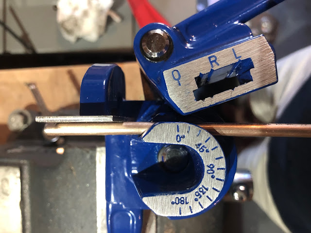
Having cracked the flaring operation I moved onto advanced bending and discovered some issues with the pipe bender that I had purchased.  The tool is actually made by Eastwood (a US company) and is marketed specifically for bending brake and fuel hard lines from 3/16" to 3/8".  Actually, the three channels in the tool are actually sized for 1/4", 5/16" and 3/8" and the instructions simply state that for bending 3/16" to use the 1/4" channel.  All well and good but there is quite a difference in diameter between 3/16" and 1/4" (4.76mm vs 6.35mm) and 3/16" pipe sits very loosely within the bending channel and does not align properly with the 'stop edge' on the tool.  I ended up inserting an offcut of 2mm steel sheet between the pipe and stop edge while bending to get the pipe alignment correct in the tool.


3/16" Pipe does not sit square against "stop edge" (circled)


Using 2mm Steel spacer to correct pipe alignment in bending tool


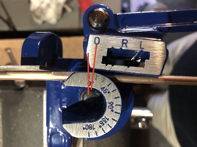
Making a bend in a piece of pipe is as simple as inserting the pipe into the appropriate channel on the tool and supporting one end by the stop edge (with optional 2mm spacer...), aligning the zero degree marks on the stationary arm and rotating arm of the tool and then pulling the rotating arm around until the zero mark on the rotating arm aligns with the desired angle mark on the stationary arm.  Again when working with 3/16" tubing it is not possible to align the zero marks properly, and so bending to a specific angle actually requires a bit of guesswork and frequent checking with an angle finder/protractor.

Misalignment of Zero marks with rotating arm seated on 3/16" pipe 

Rotating arm pulled round to bend pipe just beyond 45-degree mark...

...however, bend is actually not quite 45-degrees


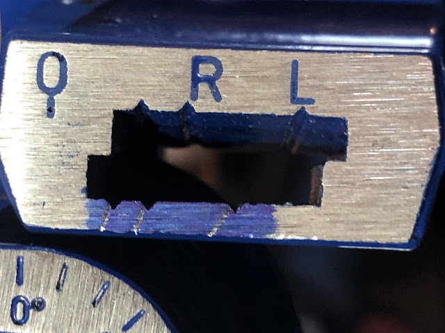
Now, this method is fine if you know where the start of any bend is on the pipe (i.e zero mark corresponds with the start of the bend).  But if you are measuring out a pipe run with multiple bends it is easier to measure the position of the bend vertices (the point where the two legs either side of the bend intersect) and then perform the bend utilising the other marks (R and L) on the tool.  And at this point, I have another issue with the Eastwood bending tool.

Clearly, at some point, the specification of the tooling has been changed, as the instructions show photos of a version of the tool with cast markings on the rotating arm and clearly identifying the marks to use for the different pipe diameters.  The version of the tool I have appears to have engraved marks and has no markings at all for the 1/4" channel (which in any case would still not be quite correct for bending 3/16" pipe anyway).  I ended up interpolating the marks for 1/4" by scoring a line extending from the 5/16" and 3/8" marks and using these as an approximation for bending the 3/16" pipe.

Eastwood instructions showing cast marks for all pipe sizes on rotating arm
(Photo courtesy of The Eastwood Company)

Extrapolated lines for 1/4" channel - unmarked notches are assumed to be the 45-degree mark (still needs some guesstimation for 3/16" pipe)


I suppose this is all a question of 'you get what you pay for" and let's face it, the Eastwood tool was a shade over £20 and a professional quality single diameter tube bender from an outfit such as Swagelok is way north of £100 which, for a single build, is just not a consideration.

So with flaring and bending techniques now sorted, it's time to make up all the necessary pipes for the Cobra.