Sunday, 13 April 2025

Lights - Part 2

To make me feel like I was actually making some progress with this build I decided to install the lights onto the car before fitting the body to the chassis (although it's taken me so long to write this blog update that the body is now on the car!).

I've gone with the classic Lucas P700-style headlights which I ordered from S&J Motors.  These come with a plastic headlamp bowl and retaining ring which also includes the adjusting screws to alter the headlamp beam alignment. 

The first task was to measure up and transfer some centre lines to the headlight openings and the front indicator positions.  This was not entirely straightforward as the molding lines on the AK body are not symmetrical!.  I measured lots of times to get this right.

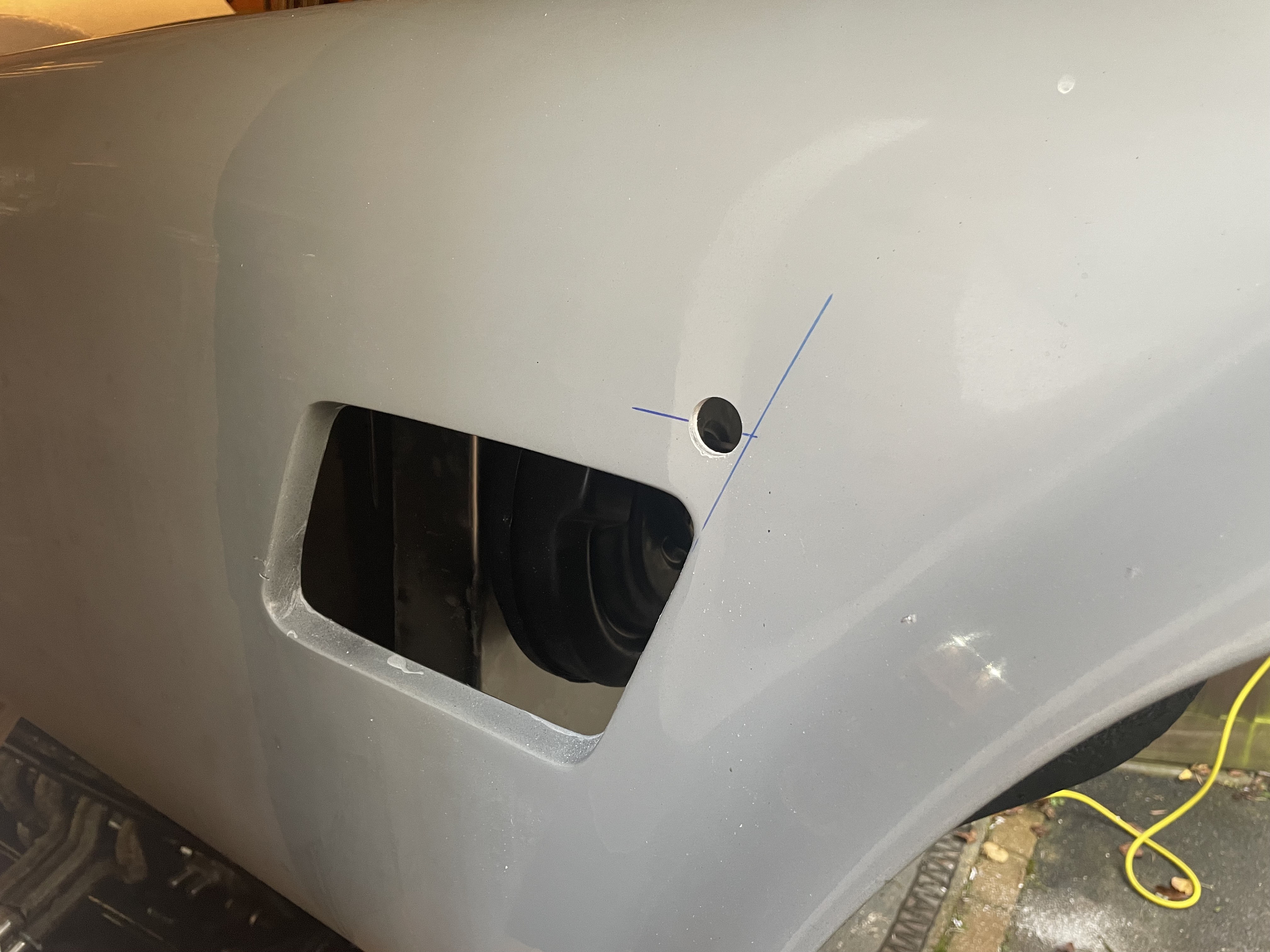
I could then mark out the required hole positions for the headlight bowls.  I did this by marking the position of the larger holes which are needed for the bosses of the beam adjusting screws and drilling these first.  I could then sit the headlight bowl flush into the opening and mark and drill the positions of the mounting screws.  The holes for the indicators were opened up with a 32mm diameter hole drill.

Centrelines marked out

Holes drilled

The headlight bowls were then fixed in place using self-tapping screws and spire clips on the back face to hold them in place.  I oversized all the holes slightly to allow some wriggle room in the final positioning of the headlights.

The headlight unit is then fixed into the retaining ring and this can be reinstalled into the bowl.  

The headlight bowl is fixed in place...

...and the headlight unit installed.

The indicator units were also fixed in place using self-tapping screws and spire clips.  The final step was to install the headlight rims.  I bought a pair of "chrome on brass" rims from Car Builder Solutions as they are less prone to corrosion than chromed steel rims.  The rims have a slight lip on the back which hooks onto the headlight bowl and are then secured in place by a single screw under the rim.  Getting the alignment of the rim correct such that the fixing screw actually lined up with its hole in the headlamp bowl was a surprisingly fiddly exercise.  

Completed front headlights and indicators

Installing the rear indicator and rear light/brake light units was much the same process as the front indicators.  Although I did spend a lot of time measuring and measuring to ensure the lights would be evenly spaced within the mounting zone on the AK body.  Again this was not so easy due to the slight differences in the body molding on each side.

Measure several times!

Holes drilled once I was happy with the location

Rear lights completed!

The last job was to install the side indicator repeaters.  These units from Car Builder Solutions just need a 20mm diameter hole to be drilled.  The mounting grommet is then installed in the hole and the LED light is pushed into the grommet from the front which fixes the whole unit in place.

Mounting hole for side repeater

Mounting grommet placed into the mounting hole...

...and side repeater and trim ring pushed into the grommet.

It's a small thing but getting the lights installed has started to make the project look more like a car now and hopefully, it will motivate me to get moving on with the build!


Lights - Part 1

I have chosen the Lucas L488 style Indicators and Stop Lights for Project Snake as I preferred the flatter profile of the lens glass to the alternative domed style lens.

Lucas L488 Style Indicator

These were fitted as original equipment on many British cars in the 1960s and 1970s.  I bought my units from S&J Motors and they still appear to be as per those original units, even down to needing to use Lucas brass bullet connectors to connect the wiring!

The rubber backshell holds the lens glass and the chrome trim ring in place and protects the wiring connections.  There are three holes in the backshell for wires to pass through.  However, these holes were much larger than the diameter of wire that I was planning to use (20AWG thin wall insulation from Car Builder Solutions) so I decided to add some wiring pigtails from the bulb holder to a weatherproof connector and seal the wiring with heat-shrink to keep it watertight.

Disassembled Light Unit and a Lucas Brass Bullet Connector

Using a special tool, the Lucas brass bullet connectors are crimped onto the wire.  I wrapped the wires around the bulb holder a few times to allow the bulb holder to be pulled out from the backshell in the future should the need arise.  I passed all the wires through one of the holes in the backshell, the other two will be plugged with Tigerseal or similar to keep water out.

Bullet Connectors crimped onto wires

I used a short length of heat-shrink tubing around the wires as they exited the backshell.  I also used a small piece of adhesive-lined lined heat-shrink to seal around the exit from the backshell and the wires; the adhesive melts and forms a weather-tight seal around the wires.

A (hopefully) weather-tight seal as the wires exit the backshell

For the connector at the end of the wiring pigtail, I have gone with Deutsch DTM connectors.  These are one of the 'go-to' electrical connectors in the high performance automotive market and offer great reliability and ability to endure harsh environmental conditions.

They use a Size 20 solid-barrel contact which is rated to 7.5Amps and can accommodate 20-24AWG wire.  

Typical DTM connector parts - Size 20 pin and socket contacts

Contacts are crimped with a special tool - note the pairs of indentations around the base of the contact

The pins are then inserted into the rear of the connector body, passing through a silicon wire seal, until they click into place.  A wedge lock is then inserted into the front of the connector body, which holds the pins or sockets in place and prevents them from coming loose.

Again I used a short length of adhesive-lined heat-shrink around the end of the connector body to seal around the body and the wires to keep it all weather-tight.

Full set of indicators and weather-proofed wiring pigtails


Friday, 11 April 2025

Body Preparation - Part 3 - Holey Moley Batman!

Another task required before the body could be installed was to cut holes in the floor pan for the gear lever and for the fuel tank filler neck and access to the fuel gauge sender unit.

To locate the hole for the gear lever, I made up a jig from a couple of pieces of strip wood.  This was located in the body mounting holes in the chassis and then I fixed a laser level onto the jig and aligned it with the centre of the gear lever.

Wood and Laser Level Jig

I measured the distance from the laser level's edge to the gear lever's centre. I then aligned the jig into the body using the mounting holes in the body to locate it and measured the distance from the edge of the laser level to the top of the gearbox tunnel to find the centre of where the hole for the gear lever needed to be.  I then cut the hole for the gear level using a 120mm diameter hole saw.

Locating the centreline of the gear lever on the body

One gear lever hole added
 
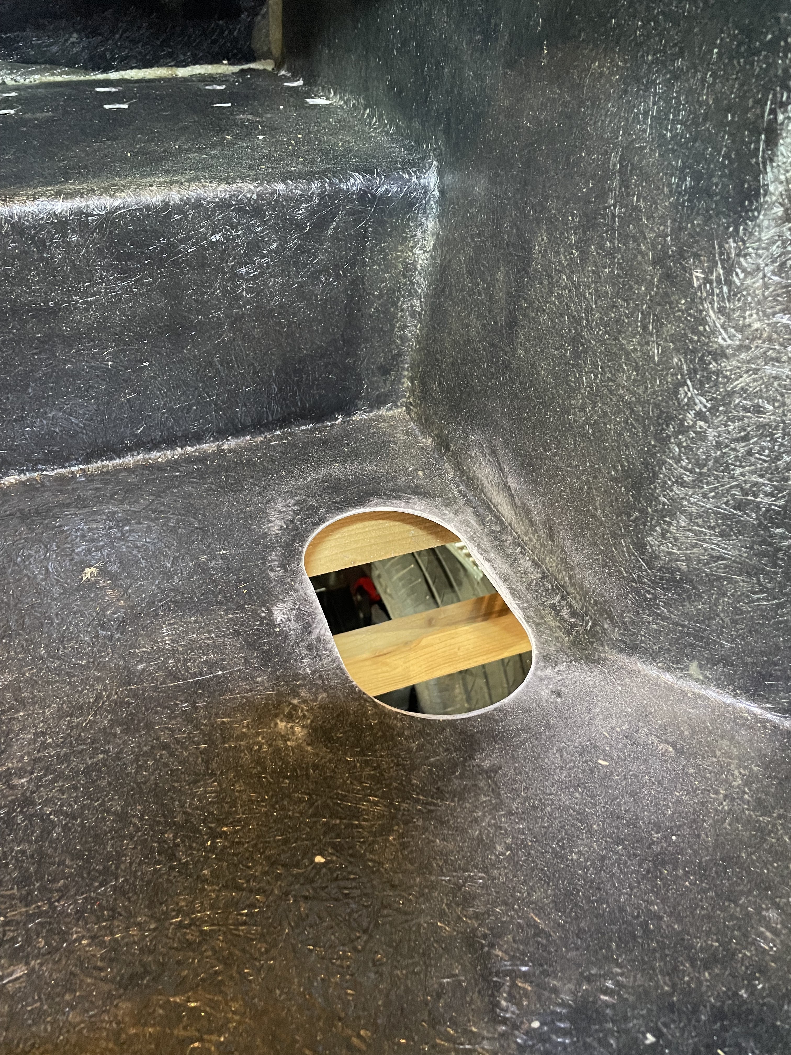
For the hole in the boot floor, I made a template out of a piece of cardboard, which used the two body mounting holes in the rear chassis cross-member as a location reference.  I transferred the template to the body and marked out the hole location.  Again I cut out the hole using a 120mm diameter hole saw for the ends of the opening and a multi-tool to cut the edges of the opening.

Cardboard template for hole in boot floor...

...transferred to the body...

...hole position marked...

...and cut out.

The last thing I did before getting the body on for its first trial fit was to put some foam tape along the top of the chassis rails.  The AK build manual suggests running a large bead of sealant on top of the chassis to seal the body to the chassis.  Obviously, as I intend on removing the body again at some point, I did not want to carry out this step.  However, using sealant, even in the permanent case would make any future body removal very difficult so I have elected to substitute the sealant for some 5mm thick closed-cell foam tape.

Self-adhesive foam tape around the chassis rails

Now I just need a nice day and a few friends around to get the body on for the first time!


Friday, 7 March 2025

Steering - Part 3 - Steering Column Preparation

The steering column for the AK427 is provided by a BMW E34 unit (which comes from any BMW 5 Series from 1987 to 1996).  I acquired a used unit from the well-known internet auction site when I ordered my kit.  You must ensure the column is complete, including the lower extension piece and the bolt that holds the steering wheel in place.  My column did not include the plastic cowling and I did have to search around to get both the top and bottom sections; I ended up buying them separately.

BMW E34 Steering Column

The ignition barrel and steering lock mechanism need to be removed from the original column as they will not be needed in the final set-up.  The ignition barrel supposedly can be removed by "simply" inserting a stiff wire or narrow probe (I used a 1mm allen key) down the small hole on the face of the ignition barrel to depress a spring-loaded key that locates the barrel in place.  I spent a joyful hour trying to get that to work before I resorted to drilling a small hole into the side of the barrel and using a small screwdriver to depress the key and remove the barrel (which took less than 5 minutes).

To remove the barrel, insert a pin into this hole...
..
...although drilling a small hole here...

...and inserting a small screwdriver...

...is far quicker!

The rest of the ignition barrel mechanism is removed by grinding down the sides of a small boss on the bottom of the ignition housing until it is possible to grip the pin in the middle of the boss with some pliers and pull it out.  The rest of the mechanism can then be easily extracted.

Grind down the boss to expose this pin...

...pull the pin out...

...and pull out the last bit of the ignition barrel.

This still leaves the steering lock mechanism in the barrel.  The easiest way I have found to remove this is to undo the two security bolts holding a plate onto the top of the barrel housing.  I cut a slot in the top of each one using a dremel and used an impact screwdriver to undo them.  This allows the ignition barrel housing to be removed from the steering column and exposes the steering lock mechanism, which can then be levered out and removed.

Two security bolts on top of the ignition barrel housing...

...in the process of removal...

...which then exposes the steering lock mechanism...

...allowing all the components to be removed.

The BMW column mounts need to be modified to fit the AK body.  This involves trimming the top mounting plate of the column and cutting off the left-hand leg of the column mount.  

The top mounting plate needs to be trimmed...

...to leave around 40mm left protruding...

...and the left-hand leg of the column mounting...

...is removed entirely.

The last "modification" required is to remove the large nut from the end of the lower column section.  From Russ Howell's video series, I know that this nut can clash with the side of the pedal box and that AK had advised the nut is not really needed and can be dispensed with.  Easier said than done, as the nut on my column was stuck fast and no amount of leverage and gentle persuasion could budge it.  I resorted to cutting a slot in the side of the nut with an angle grinder and using a cold chisel to split the nut off the shaft.

The large nut on the lower section of the column...

...needed some minor surgery to aid its removal.

I gave the exposed metal parts of the column a couple of coats of black Smoothrite before reassembly and bought a new rubber steering joint for between the upper and lower column sections.  The column is now ready for installation! 

The modified steering column ready to fit!


Friday, 13 September 2024

Handbrake - Part 2 - Installing a Linear Particle Accelerator

The normal handbrake set-up on the AK Cobra is a cable-operated system, utilising an XJS handbrake lever in the cockpit, operating a lever mounted above the differential unit that in turn pulls on the handbrake cables connected to each rear hub.

The original AK handbrake set-up, whereby the cable simply pulled directly on the actuator lever, did appear to have a reputation for not being very efficient (based on a read of several internet forums).  AK has addressed this and modified the set-up with the cable operating the lever via a pulley set-up to provide twice the pulling power.  Improved, but still a bit touch and go come IVA / MOT test time.

AK Handbrake Modification (from AK Build Manual)

I decided to make a couple of further modifications to the system myself to improve the handbrake performance.

The first modification involves the XJS handbrake lever.  I obtained the lever from Simply Performance at the same time as my donor axles.  The photos below show the lever before and after modification...

XJS Handbrake Lever before initial modification...

...and after modification!

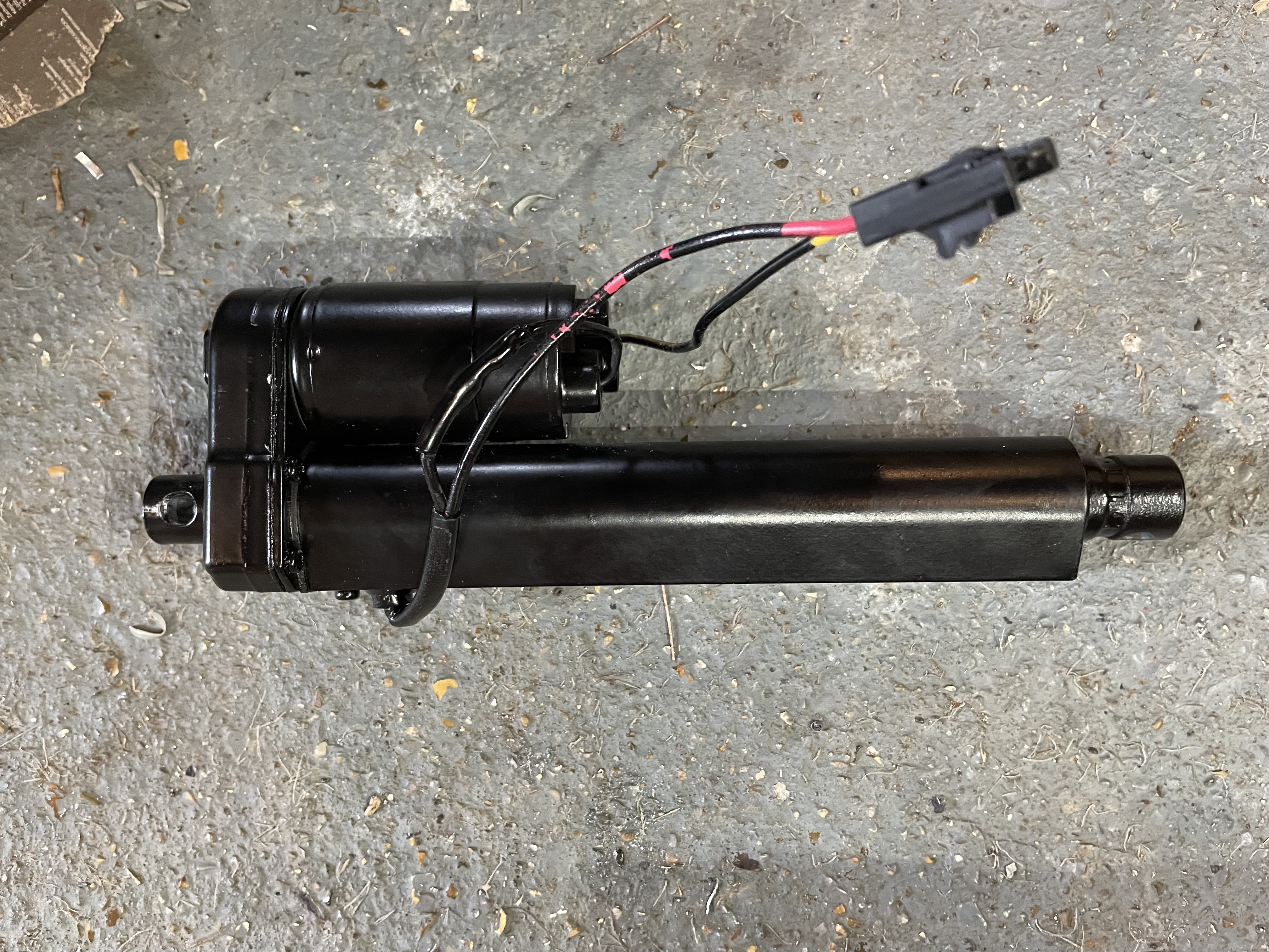
The second modification involved the purchase of an electronic handbrake kit from Hollin Applications Ltd.  This kit was developed for the Motability market in the UK but seems to have gained popularity with many Cobra builders over recent years. The kit includes a linear actuator, an electronic controller and a simple switch.  The controller enables the pull / push force on the actuator to be adjusted up to a maximum of 800N or 80kg in old money.  It also meets the IVA requirement of preventing the handbrake from being released unless the ignition is switched on (it does also have the problem that the handbrake can't be released if the battery goes flat - but we will cross that bridge later).  The switch is a bit basic and will do for initial testing, but it will be replaced with something to match the other interior switchgear (when I decide what that will be...)

Linear Actuator

A bracket of some description is needed to mount the actuator to the rear chassis cross-member.  Since I made the decision to go with the Hollins kit, AK has actually started using them in their factory builds and has started selling an electronic handbrake kit including a mounting bracket.  However, I felt the price they were asking for the bracket alone was a bit steep and as I enjoy spending valuable time that I haven't got, making unnecessary bits for this build, I decided to make my own...

Fortunately, I got a bit of a headstart via Steve Sutton's build blog which referenced a solution by another builder Michael de Kok, who had included the details of the bracket he had fabricated for his own Cobra electronic handbrake install.  So, giving credit where it is due, I have borrowed the same design.

I completely forgot to take any photos of the fabrication process, so thankfully you can all just see the final bracket before and after powder coating!

Final bracket before coating (don't be too harsh on my welding)...

...and after powder coating

I fitted the handbrake actuator to the bracket using a long M6 bolt with a couple of spacers that I machined from some offcut of steel bar.

The actuator is installed into the bracket.

I then drilled and tapped some holes in the rear cross-member and fixed the bracket/actuator to the cross-member with some M8x1.25 bolts and spring washers.

The handbrake actuator & bracket are fixed to the rear cross-member.

I also needed to replace the operating lever from the item that AK supplied.  I fabricated a new lever from a 5mm thick steel plate with a small section of steel channel welded on the end.  The channel end needed to be reworked with some light grinder action to prevent the lever from fouling on the chassis at full throw.

New handbrake operating lever

I trial-assembled all the bits and wired up the control board temporarily to test out the operation.  Thankfully it all seemed to work OK with the actuator shutting down at extension once the load from the handbrake cables started coming on; the control box is preset from Hollins at 50kN load.


The final assembly involved powder-coating the operating lever, making up a couple of nylon spacer washers and bolting it all back together with copious amounts of copper grease.

Final handbrake assembly