Showing posts with label New Parts. Show all posts

Sunday, 17 May 2026

Fuel Filler

I have gone with the classic Aston-style fuel filler cap, which I ordered from Brasscraft at the same time as the windscreen.  This comes in two parts: the lower mounting flange, which incorporates the locking fuel cap and the Aston-style cap itself, which screws onto the flange. I also ordered the unleaded fuel insert, which is needed to prevent a diesel fuel pump from being inserted into the fuel filler.  This is inserted into the bottom of the mounting flange and held in place by a wire lock-ring.

The fuel filler-cap components

The unleaded insert in place, and the wire lock-ring

I located the centre of the recess in the AK body, using a machinist block to draw several chords across the circular recess, and drew a line perpendicular from the centre point of each chord, which should pass through the centre point of the recess.  It does pay to do this several times, as I clearly had one line not lining up where it should!

Spot the line not playing ball!

I used a 76mm diameter holesaw to form the hole for the mounting flange.  I fitted the cap to the flange and checked that the cap hinge did not clash with the deeper edge of the recess.  It did, so I used a file to open up the hole slightly towards the rear of the body.

Hole drilled...

...and the flange inserted.

Initially, the hinge hits the body when the cap is opened.

The mounting flange comes undrilled, so the next step was to take a deep breath and get the drill out.  Thankfully, the positions for the holes are marked out on the underside of the flange.  I drilled the holes with a 4mm diameter bit using WD40 as a cutting lubricant.

Dimples identify the location of mounting holes

The easy part was drilling the holes.  The holes need to be countersunk on the top side of the flange.  I had a metal countersinking bit but its diameter put it far too close to the threaded part of the flange for my comfort.  I've seen on other build blogs people use an 8mm drill bit to form the countersink; i tried that but it left a very jagged finish.

I ended up buying a cheap metal countersink set from that well known internet auction site, which had bits of varying diameter, plus a round ended carbide cutter.  I used an 8mm diameter countersink bit first and then used the round end carbide cutter to smooth the rough edges.

My usual metal countersink bit would not align with the hole

A smaller countersink bit and a rounded carbide bit did the job

I did a test on the underside of the flange to make sure I was happy with the finished result before countersinking and rounding off all the holes on the top side of the flange.

All holes countersunk

With the cap screwed onto the flange, I could then align the cap so that it was a) positioned correctly for the IVA requirements and b) not fouling on the bodywork when the cap was opened.

I could then mark the positions of the holes and drill them out for the 4mm countersunk mounting screws.

Mounting holes drilled...

...and flange secured with M4 countersunk screws

Cap installed and in the correct orientation

Another top tip - when marking out the locations for the mounting bolts, make sure the cap is secured tightly onto the flange.  I thought I had it on tight enough, but when I first secured the flange and screwed the cap on, I could tighten it an extra 20 degrees or so from where I had it previously.  As a result I had to drill all the mounting bolt holes again.

Next up was to connect the filler cap to the fuel tank.  The fuel filler hose is 51mm diameter reinforced ultra flexible hose from Car Builder Solutions.  I used a spare length of braided fuel line to connect to the vent on the tank, which was connected to an alloy T-piece pipe connector ordered from eBay.

Hole drilled for fuel filler pipe using a 50mm holesaw

Fuel filler hose and vent installed in boot...

...and under the rear wheel arch

I need to get some hose ends for the vent hose to complete the job, but until then, that's another thing crossed off the long to-do list!

Tuesday, 21 May 2024

Steering Part 2 - Power (Steering) Struggles

So my power steering issues still need to be fully resolved...

With my pump issues sorted (See Engine & Gearbox Installation - Part 6) all I needed was to connect up the pump reservoir and hoses and all would be good.

Haha...

Having bought the billet ancillaries bracket from Kyle at LSX Performance I knew that I wouldn't be able to use the standard LS Power Steering reservoir which, as I understand it, slots into the standard Chevy ancillary bracketry.  Kyle did supply me with an alloy tank to suit the kit he had provided, but in the end, I decided there were a couple of issues with it.  

Firstly, the low-pressure spigot on the tank was far too small for the AK-supplied hose and I was worried that I would not be able to get a tight enough seal with a jubilee clip (the AK hose is also braided which restricts the ability of the hose to crush down small enough).

The second issue was that with my shiny header tank and washer tank, the alloy version just didn't really meet my required "bling" standards.

It's good - but not good enough...

This led me to design my own version of the reservoir which utilised some AN-style fittings that would match the size of the low-pressure hose and the inlet port on my power steering pump.

CAD Design for new reservoir...

...using -AN weld-on fittings

I rang around a couple of companies to get a quote for making up my design in polished stainless steel.  I ended up going to XCS Designs, perhaps better known for their own Cobra kits, who are just up the road from me.  Scott, their Workshop Manager, gave me a pretty reasonable quote on the basis that I provided the AN fittings and a weld-on filler neck (which I obtained from that well-known auction site).

My only real issue with that decision was that XCS was going through a particularly busy period (which is good for them) and I had to wait several weeks before my reservoir was ready.  But I think it was well worth the wait!

New shiny reservoir!

Once I had picked up the tank and was ready to install it, I realised that sometimes it pays to just take a little more time planning and thinking things through fully...

The first issue was that on my original tank, the output spigot at the rear was installed right at the bottom of the tank.  In my new design, with the weld-on -10AN fitting, it now sat slightly higher up on the rear of the tank.  This meant that the collar of the AN fitting just clashed with the billet ancillary bracket and prevented the tank from sitting flush against the bracket...

Original tank outlet - at very bottom of the tank...

With weld-on AN fitting, the outlet sits higher on the rear of the tank...

...resulting in the collar of the weld-on fitting clashing with the ancillary bracket

The second issue was that, despite measuring several times, the holes on the new tank did not quite align with the bolt holes on the ancillary bracket.  Comparing the hole positions with the original tank showed them to be quite a way off.  Again, a stark reminder to plan properly and keep checking everything several times and then check again...

The second issue was actually relatively easy to resolve simply by drilling out the mounting holes on the new tank from 10mm to 12mm diameter with a hole drill.  This gave enough wriggle room to get the bolts through the mounting tabs and into the holes on the ancillary bracket.  The added bonus was that by allowing the position of the tank to shift slightly, also solved the first issue above, and the tank now could sit flush against the ancillary bracket.

However, the third issue then identified itself.  I bought a 90-degree -10AN fitting to attach to the rear of the tank and then connect to the -10AN fitting on the inlet of the power steering pump.  However I had failed to consider the dimensions of the -10AN fitting on the back of the tank, and with this installed, there was insufficient space between the front and rear of the ancillary bracket to allow the tank to sit flush as intended.

AN fitting hard against the bracket preventing the tank from sitting flush

This was not a major deal (although it was annoying) as I was able to turn up a couple of 12mm thick spacers from some 20mm diameter aluminium bar with a 10mm diameter hole drilled through the middle.  I also had to buy a couple of slightly longer 10mm diameter bolts to account for the additional thickness of the spacers.

Finally, I could get the tank mounted and the -10AN fitting and braided line routed down towards the pump inlet fitting.

Spacers provide clearance for the rear -10AN fitting

Tank in place and in need of a polish!

I used a 150 degree -10AN fitting to connect the hose to the steering pump inlet.  I originally bought a 180-degree fitting, but the -10 braided hose is not very flexible and I couldn't get the hose to align with the fitting.

150 degree -10AN fitting to align with hose orientation

I needed to angle the hose ends to align with the fitting orientations

Bottom fitting installed

The final fitting of the hose was a bit of a wrestling match.  The short -10 hose had zero flexibility and the only way I could get both ends onto the fittings was to take the reservoir off again, fit the hose to the reservoir and then try and connect the bottom fitting.  Once the hose was secured at both ends, I needed three hands to try and wiggle the reservoir back into place and get the fixing bolts and spacers installed.  It was a great relief when everything was finally in place and all bolts and fittings tightened!

The final connection to the reservoir was the low-pressure line return line from the steering rack.  This is another braided line supplied by AK.  It is installed to the steering rack with a banjo fitting and then routed up to the reservoir.  I used a 60-degree -8AN fitting to connect the hose to the reservoir.

Low-pressure return line from Steering Rack completed

Now all I need to do is get a new high-pressure hose made up with a -6AN fitting on the pump end and this job will finally be done!!!

Saturday, 16 September 2023

Exhaust & Headers - Part 1 - Initial Fitting

I have gone a slightly different route, it seems, from most of the other AK LS builds out there at the moment.  The majority of builders appear to have used the standard GM LS headers (either LS3 or LS7), I suspect for no reason other than they were supplied with their engines.  Not that that is an issue, both the LS3 and LS7 stock headers are pretty well matched to the engine and perfectly adequate for most street-driven applications.

However,  my engine was supplied without any exhaust headers.  Now I could have probably tracked some factory GM items (although when I initially looked there were not that many around) but I kind of like the look of proper tubular headers in the engine bay and, despite the cost, I knew that really I was always going to go down the route of buying the AK stainless steel headers and side exhaust system.

AK can supply headers in two diameters 1 5/8" or 1 7/8"; the former is typically for LS3 builds and the latter for LS7.  I had a chat with Jon about which size to go for. His view was that the smaller diameter headers would be a better option; typically larger diameter pipes are good for higher horsepower and high revs, while a smaller diameter is better for low-end torque and a better option for "normal" driving.  Looking online, I found that most LS aftermarket tubular headers are 1 3/4" in diameter so I went with the smaller AK option.  Which turned out to be quite handy as Jon had a complete set of 1 5/8" headers and side pipes on the shelf from a customer who no longer wanted them!  And so a week later they were in the boot of my car and on their way back to my garage.

AK Stainless Steel Tubular Header

Set of Exhaust Gaskets from LSX Performance - complete with instructions!

Comparison of Exhaust Port D shape/size in relation to Header tube size


Initially, I installed the headers onto the engine without the gaskets and just with a couple of bolts to hold them in place.  I can see that with the additional Gen III chassis bracing getting the front header bolt in place and tightened up on both sides will be fun.

Shiny tubes!!

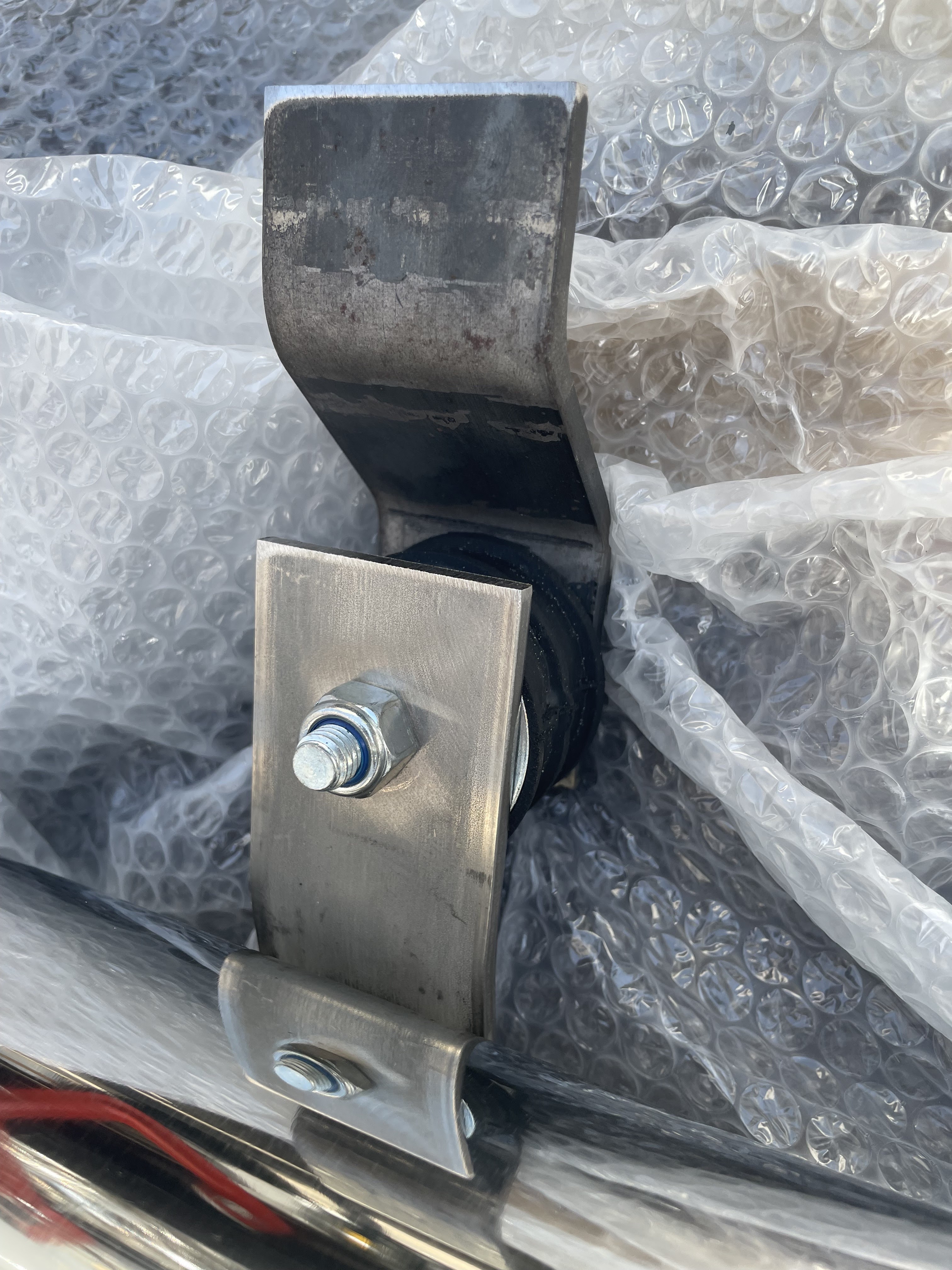
The AK side pipes come with some mounting brackets and rubber bobbins (which look suspiciously like engine mounts!) which sit between the side pipe and the bracket.  

Rubber bobbin between side pipe and mounting bracket

The brackets are intended to be welded to the chassis but, following the example of many other builders, I am going to bolt them on and use a threaded bung welded into the chassis for added strength.

Firstly I marked the centre line on the top of both brackets and then bolted the bobbins and brackets to the side pipe (with the bobbins bolted in the centre of the slotted end of the bracket to give some adjustability), slid the pipe onto the headers and then used a couple of clamps to hold the whole assembly in place.  (I put plenty of blankets and bubble wrap down on the floor to prevent any damage in case I dropped the side pipe in the process!).

I could then finagle the side pipe backwards and forwards until the distance between the pipe and chassis was the same at both mounting positions.  I ended up with the pipe approximately 85mm set off from outside the chassis rail on both sides.

Offside side pipe is temporarily held in place...

...and the same for the nearside side pipe

Offset from chassis approximately 85mm

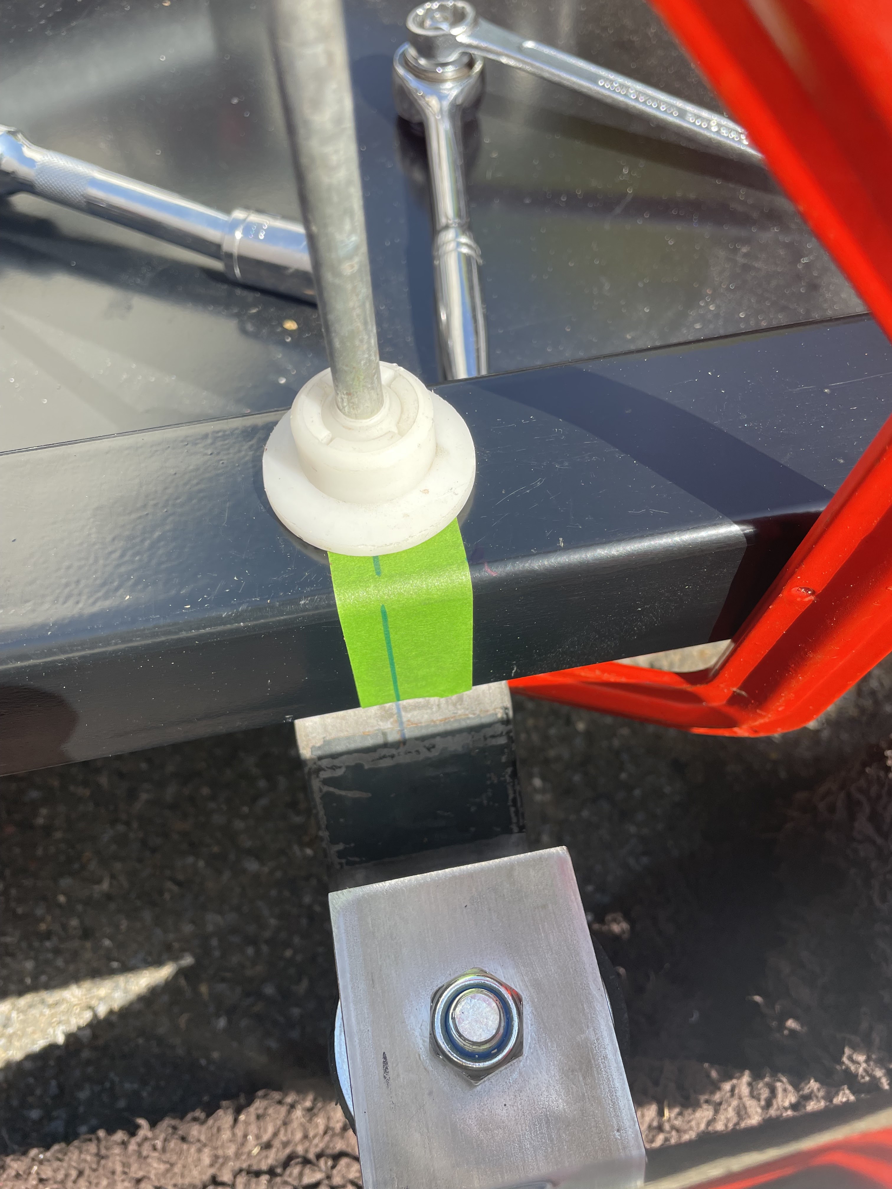
Ensuring that the brackets were at 90 degrees to the chassis rails I stuck a bit of tape on the chassis and transferred a mark for the centre line of the bracket onto the chassis.  I drilled a 10mm diameter hole through the top and bottom of the chassis rail and opened the top hole up to 20mm with a hole drill at each bracket position.  I could then drop in a couple of bungs made from 20mm diameter steel bar into which I drilled and tapped an M10x1.5 threaded hole and once I had drilled a 10mm diameter hole into the mounting brackets, these could be fixed into place with M10x30 bolts.

The centreline of the bracket transferred to tape on the chassis

20mm Diameter bung threaded for M10x1.5 on the underside

The last job was then to drill a 10mm hole in each of the mounting brackets, which I also powder coated in gloss black ready for final installation.

Bracket after drilling and powder coating

I then re-wrapped the side pipes in bubble wrap and put them away until the body is mounted and the pipes will need to be fitted into place again to finalise the position of the hole in the body.


Sunday, 18 June 2023

Heating and Cooling - Part 2 - Radiator Plumbing

 A few weeks back I took a trip to AK to pick up various shiny parcels and to give my credit card a sharp intake of breath...

The shiny parcels included my side pipes and headers, but also the air inlet pipe, the radiator header tank and the top and bottom radiator pipes.  

This meant that I could get on with plumbing in all the radiator hoses.

Shiny new radiator header tank

The first job was to swill the header tank out with some water to remove any detritus that remained lurking within.  I then filled the tank with water and bunged up the bottom outlet pipe for an hour or so just to check that there were no pinholes in the welds that would leak.

No leaks from welded joints!

The header tank is mounted to a cross-member at the front of the chassis.  I marked the centreline by measuring between the two radiator top-frames and then marked two lines 50mm on either side to allow for the diameter of the air inlet pipe.  I then marked another line midway between the "edge of inlet pipe" line and the radiator top frame and then centred the mounting holes for the header tank on either side of this.

Centres for mounting holes measured...

I then centre-punched the holes, drilled out to 6.8mm, and tapped for an M8x1.25 thread.  The header tank was then installed using 2No. M8x20mm stainless steel bolts with spring washers.

Header tank installed

The radiator top hose was connected up next.  AK supply a stainless steel section of pipe which is joined to the radiator and to the engine with some lengths of flexible hose.  I had measured the stubs on the engine and the radiator to determine the hose bore needed and had purchased some 35mm bore silicone hose.  The AK stainless pipe is actually around 38mm outside diameter, so while the 35mm bore silicone hose could be squeezed onto the stainless pipe, it was a tight fit.  To my mind, however, this was the right thing to do; using a larger bore pipe to fit onto the stainless pipe would result in a looser fit onto the radiator and engine stubs and, while the silicone hose might be compressed enough to seal when tightening up the jubilee clips, I think having a tighter fit in the first place presents less risk of leaks.

AK supplied Top Radiator Pipe...

...installed in place with a short length of silicone hose at each end

Thinking ahead I angled the tightening screws on the jubilee clips securing the silicone hose at the radiator end so that in future they can be accessed from the side or below; once the body is on, access from the top will be impossible and it's very tempting to just secure these clips with the screws pointing upwards!  All the hose clips were tightened to 5Nm torque and rechecked again after 30 minutes or so to allow for any relaxation of the silicone.

Next up was the connection between the header tank and the small pipe on the top of the engine which connects to the water galleries in the cylinder heads, and the header tank overflow pipe.  I used some silicone hose with a bore of 6.5mm for both of these.  I secured the overflow pipe with a couple of P-clips secured with some M6 button screws to the radiator top frame and the bottom chassis rail.

Small diameter pipe between header tank and engine

Overflow pipe secured using a couple of P-Clips

The bottom radiator hose was slightly more tricky to fit.  The bottom hose has three connections; one to the bottom of the radiator, one to the bottom of the header tank and one to the thermostat housing on the engine.  The connection to the radiator bottom outlet was made with a length of 35mm bore silicone hose (same as the top hose).  The connection to the header tank was made with a length of 25mm bore silicone hose. I needed to support the bottom stainless pipe roughly level to be able to judge the correct length to cut the required length of hose.  I erred on the side of caution and initially made the hose too long and cut it down 10mm at a time until the right length was achieved.

The connection to the engine thermostat was more involved.  Other builds I have seen have just used a 90-degree silicone hose bend between the thermostat housing and the vertical section of stainless steel pipe (the angle is slightly more acute than 90 degrees but the silicone hose gives some flexibility to adjust).  

I had ordered a 90-degree 35mm bore silicone bend thinking this would suit the purpose.  Unfortunately, I discovered two problems.  The first was that the leg lengths on my 90-degree bend were too short so when the bend was slid onto the vertical stainless pipe, it didn't reach the thermostat housing.  The second problem was that the diameter of the thermostat housing is 42mm and no amount of cajoling would get the 35mm bore hose onto the outlet.

My solution was to order a 38/35mm silicone reducer plus a couple of alloy 35mm hose joiners assembled as shown in the photos below. Ideally, I would have ordered a 40/35mm reducer but Merlin was showing it out of stock for 6-8 weeks and I wasn't prepared to wait that long.  You might ask why I didn't just do the whole section in 38mm bore hose, which might have been simpler, but as I had already bought the 35mm 90-degree bend I wasn't too keen on just binning it.

AK Bottom Radiator Pipe

My solution involves a reducer, some joiners and a 90-degree bend...

...all fully assembled

As installed on the car

The hose from Header Tank to the lower Radiator Pipe

The last hose to fit was the pipe from the header tank to the top of the radiator.  Unfortunately, I hadn't thought this one through fully; the routing of the pipe is quite tight and very dependent on the position of the wash/wipe water tank, which I had not yet ordered.  So there was another short delay in the proceedings while I ordered the second tank from AK Sportscars and awaited delivery.

Once it arrived I fitted it in the same manner as the radiator header tank.  I could then route the final silicone hose, fix a P-clip in an appropriate spot, and that is another job complete!

Routing of the final section of radiator hose

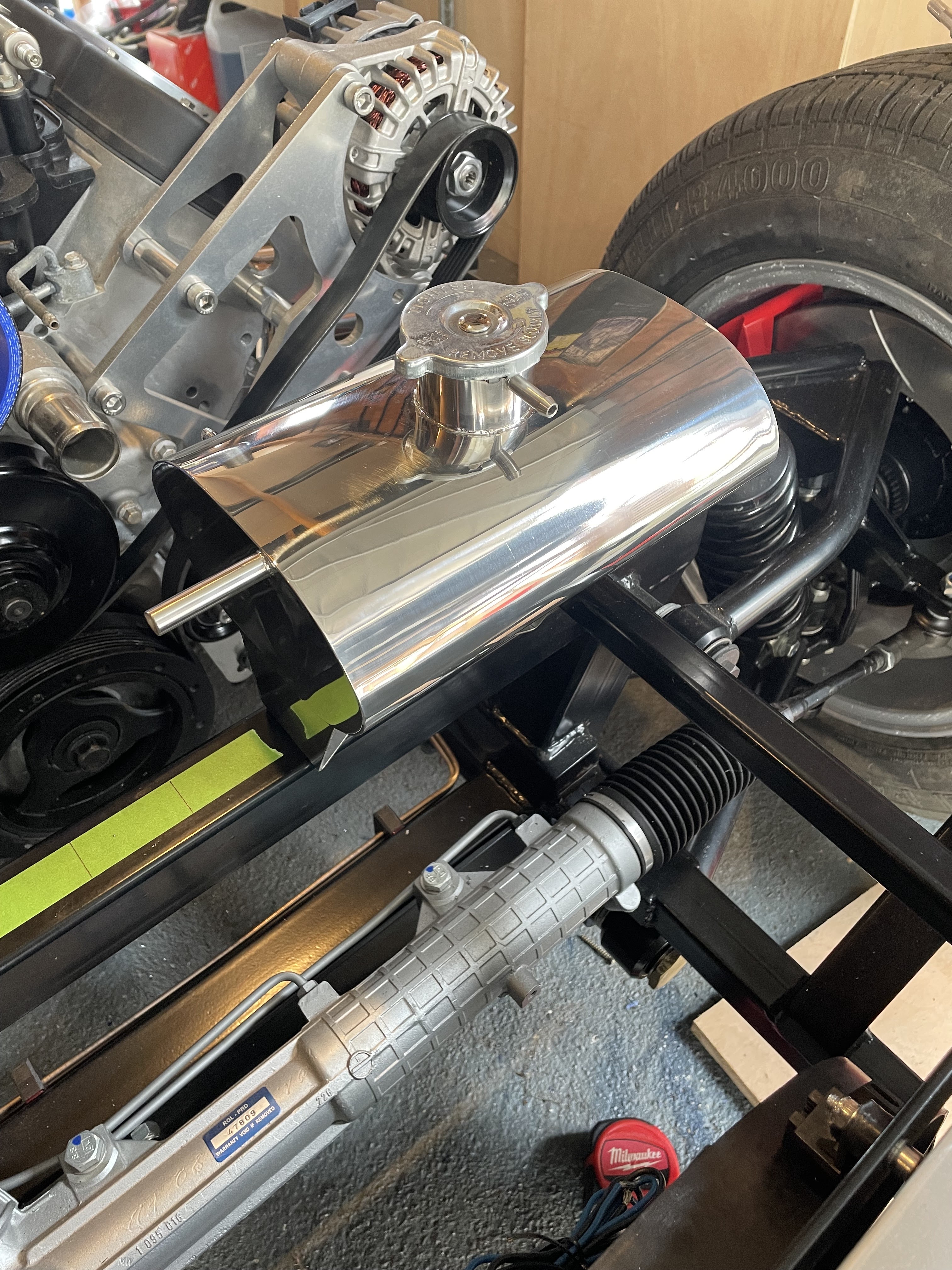
Not quite relevant to this post - but both bling tanks are in place!!