I decided to install the steering column before fitting the body to the chassis because, while the body is supported on its frame, I considered the height would make it easier on my ageing back!
On the face of it, this should have been another relatively straightforward job, and, as usual, it turned out to be anything but.
First things first, a bushing is needed to support the lower extension piece of the column as it passes through the driver's footwell bulkhead. This part is made specifically by AK, and as it's essential for every build, I'm surprised it's not part of the basic kit (and it's not cheap).
 |
| AK steering column bushing in shiny stainless steel! |
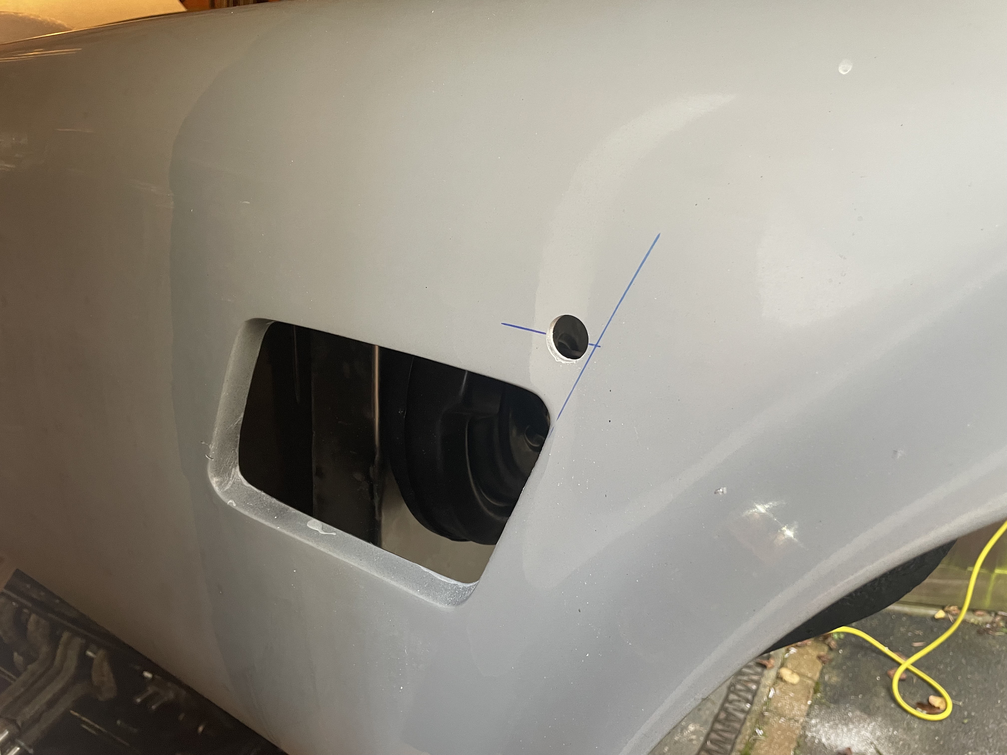
I started the installation in the engine bay - another reason for doing this job while the body is off the chassis. AK had already drilled the hole for the steering column in the driver's footwell. My plan was to try and fix the bushing more or less centrally over this hole, thus avoiding the steering column rubbing anywhere as it passed through. I used a ruler placed against the pedal box mounting bolts to establish a vertical line and then set out the mounting positions for the bushing. The mounting holes were drilled using a 5.5mm diameter drill bit. I also tidied up the AK-drilled hole in the bulkhead with a stepped hole bit just to remove the sharp edges.
 |
| Some accurate setting out... |
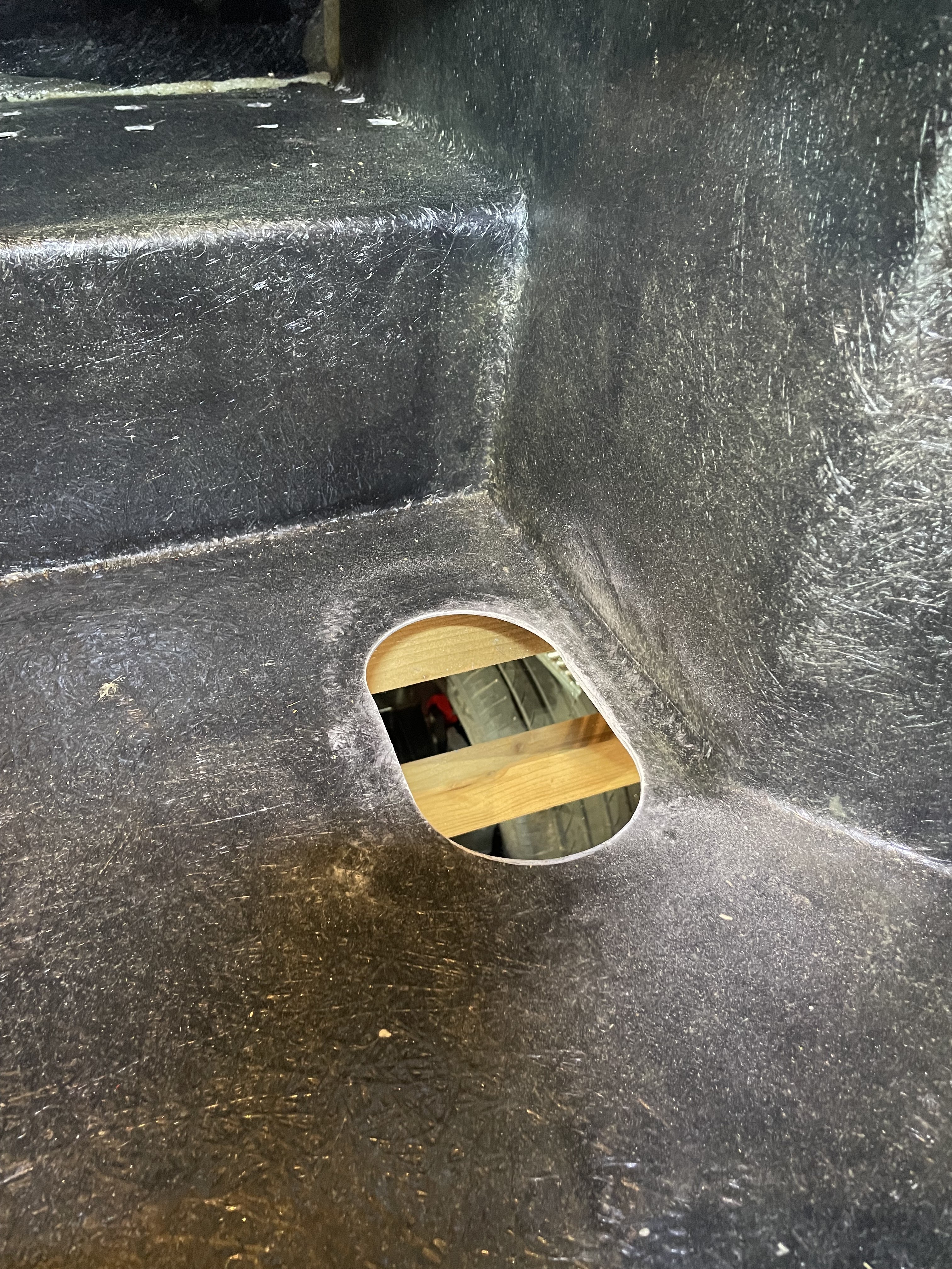
 |
| ...mounting holes drilled and sharp edges tidied up. |
Next up was to mount the BMW column unit inside the body. This should have been so simple. The AK body includes the bracketry for the two top mountings and the retained right-hand lower mounting for the column unit. These are slotted, which you might expect would give some leeway in locating the column in place. You would be wrong...!
I retained the upper mounting bushings that had come with the column when I bought it. I used two M8x30mm bolts and nyloc bolts to fix the column to the upper mounts in the body. The first problem that came to light was, that with the upper mounting bolts both bottomed in the slots in the bracket, the lower mount was around 10mm away from the lower mounting bracket and also misaligned with the slot so that I could not pass an M8 bolt through the bracket and through the column mount.
I initially solved this by sliding the column off the upper mounting bushes, attaching the column to the lower mount loosely using an M8x40mm bolt and then hooking the column back onto the upper mount bushings. There is not a lot of leeway, and the bolts seem to end up at the extremes of the slots in the AK mounts, meaning the column does not actually have any movement.
 |
| Nylon bushing in place ... |
 |
| ...lower steering column extension inserted into upper column... |
 |
| ...and the bushing housing bolted up. |
Job done! Except that the steering column was now locked solid and would not turn. Loosening the bolts holding the steering bushing housing in place did allow rotational movement to be restored so clearly something was out in the overall alignment of the steering column.
Another view of the upper column mounting confirmed that something was definitely not right with the upper mounting bracket clearly not parallel to the scuttle hoop.
 |
| Misalignment of the upper column mounting |
My solution to this issue was to remove the lower mounting bolt and put a number of washers between the steering column and the lower bracket to get the upper mounting parallel to the scuttle hoop. Fortunately, this seemed to do the trick, and rotational movement has been restored!
 |
| M8 washers used as spacers on the lower mount |